*1) Each of the connectors,
CNUSR11 and CNUSR12, are
assigned with the same pin
number, creating 2 systems in
each terminal. It is absolutely
necessary to connect the 2
systems.
*2) You can see in the diagram that
connector CNUSR2 has 2
terminals and 2 systems (16/17
indicates 2 terminals at pin
number 16 and pin number 17).
It is absolutely necessary to
connect the 2 systems.
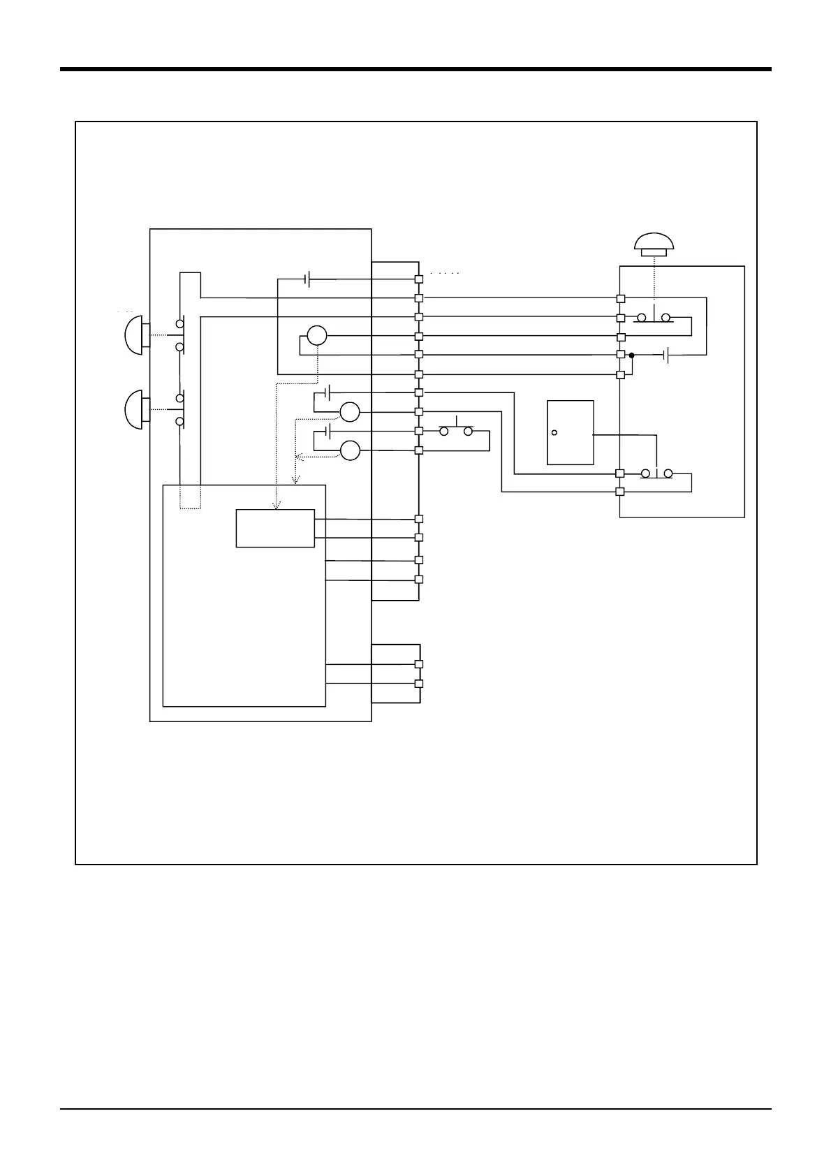
<Wiring example 2>: Connect the emergency stop switch of peripheral equipment to the controller.
The power supply for emergency stop input uses the power supply of peripheral equipment.
<Operation of the emergency stop>
If the emergency stop switch of peripheral equipment is pushed, the robot will also be in the emergency
stop state.
Controller
*3) The T/B emergency stop button connected with the controller.
*4) Emergency stop input relay.
*5)
Refer to Standard specification manual for the enabling device.
*6) The emergency stop button of the robot controller.
(Only specification with the operation panel.)
*7) The emergency stop input detection relay uses the controller’s internal safety relay control. If the
emergency stop input detection relay is switched OFF, emergency stop is detected and the safety relay
is also switched OFF.
Power supply in the
robot controller 24V
OP Emergency
stop button
TB Emergency
stop button
Not connected
Door switch input
Enabling
device
Mode output
Error output
Emergency stop output
Safety relay
Internal emergency stop
circuit
Emergency stop switch
(2- contact type)
Peripheral
equipment
Safety
fence door
Power supply in
the Peripheral
equipment 24V
*1)
*2)
*3)
*6)
*4)
*5)
*7)
 Loading...


