Controller
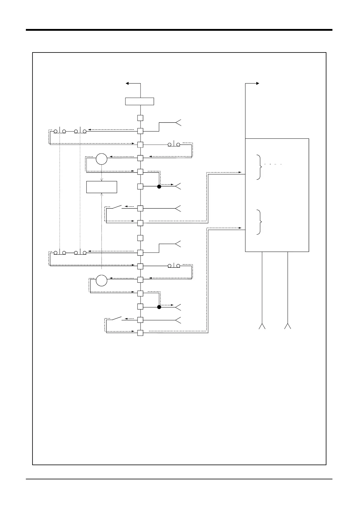
<Wiring example 5>: Connect the controller to the safety relay
Use the controller’s emergency stop button to input safety relay.
Safety relay
Internal relay
Emergency stop
output
External emergency stop switch
Customer equipment
Safety relay
ex)
G9SX-AD series *OMRON
Customer Power Supply (DC 24V)
Internal relay
Emergency stop
output
External emergency stop
switch
Safety input 1
Safety input 2
[Caution]
1) This product has category 3 functionality and therefore the robot’s whole unit cannot be set to category 4.
2) The controller’s internal circuit has polarity. Please adhere to the polarity as detailed in the wiring examples,
particularly for emergency stop button output when using user equipment. Connect the positive side of the
user equipment (24V DC) to the two terminals 26/31, then connect the emergency stop button (or contact
points) in the user equipment to the 2-27 and 7-32 terminals, and ultimately connect to the negative side
(0V DC).
3) Setup a safety relay on the user equipment, and when using to input the emergency stop button on the con
-
troller, please only use a safety relay that functions when connecting the input to the one end of the 2 sys
-
tems (i.e. Omron’s G9S Series).
4) The emergency stop input detection relay (internal relay) uses the controller’s internal safety relay control.
If the emergency stop input detection relay is switched OFF, emergency stop is detected and the safety
relay is also switched OFF.
5) When connecting emergency stop button output to an exterior safety relay, please take note of the polarity
and make sure that the electrical current flows in the same direction as indicated by the dotted arrows in the
two places in the diagram. If the polarity is setup incorrectly this function will not operate correctly. Please
connect 20/19 terminal to 24V.
 Loading...


