For users operating robots that have not been mounted with an operation panel:
Operation of robot programs such as start-up and shutdown are carried out using external signals
(exclusive input/output signals). This instruction manual is based on robots that are mounted with an
operation panel at the front of the controller, and these operations are explained using key opera-
tions on that panel. Using the parameter settings, please assign exclusive input/output signals that
correspond with each key operation to general purpose input/output signals, and operate the robot
using signal operations.
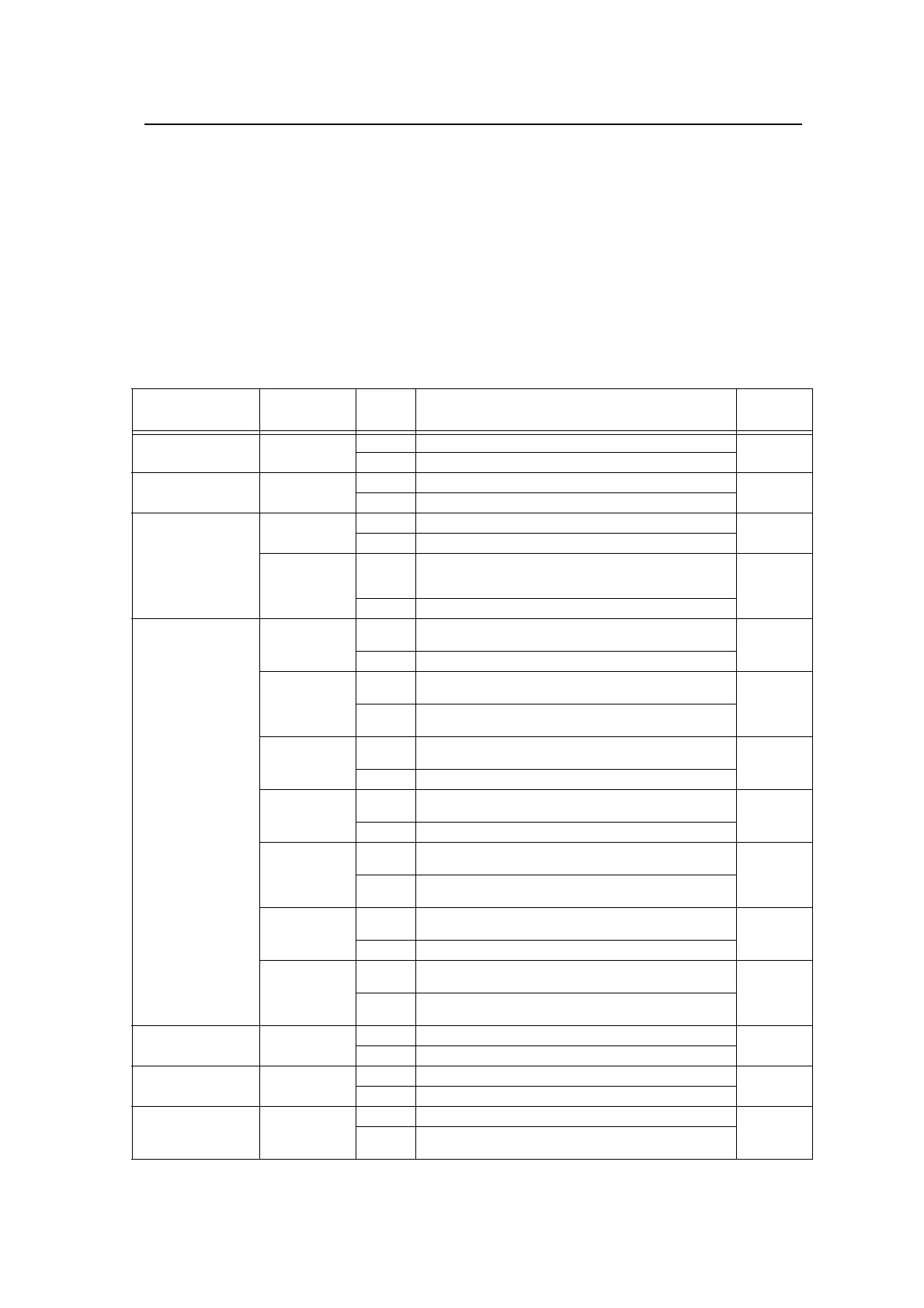
The following table details exclusive input/output signals that correspond with the key operations of
the operation panel explained in this manual. Please use this as a reference to assign signals and
operate the robot.
For further details regarding parameters please see the separate instruction manual "Detailed expla-
nations of functions and operations".
Table: Conversion table of the buttons and dedicated I/O signals
Operation panel
button, lamp
Parameter
name
Class Function
Default
setting
START button
START button lamp
START Input Starts a program. 3,0
Output Indicates that a program is being executed.
STOP button
STOP button lamp
STOP Input Stops a program. 0,-1
Output Indicates that the program is paused.
RESET button
RESET button lamp
ERRRESET Input Releases the error state. 2,2
Output Indicates that an error has occurred.
SLOTINIT Input Cancels the paused status of the program and brings the exe-
cuting line to the top. Executing a program reset makes it possi-
ble to select a program.
-1,-1
Output
Outputs that in the program selection enabled state.
CHNG DISP button
UP/DOWN button
PRGSEL Input Selects the value inputted into the signal assigned to the numer-
ical input as a program number.
-1,
Output -
PRGOUT Input Outputs the program number selected to the signal assigned to
the numerical output.
-1,-1
Output Indicates outputting the program number to the numerical out-
put.
OVRDSEL Input Sets the value inputted into the signal assigned to the numerical
input as a override.
-1,
Output -
OVRDOUT Input Outputs the override value to the signal assigned to the numeri-
cal output.
-1,-1
Output Indicates outputting the override value to the numerical output.
LINEOUT Input Outputs the current line number to the signal assigned to the
numerical output.
-1,-1
Output Indicates outputting the current line number to the numerical
output.
ERROUT Input Outputs the error number to the signal assigned to the numerical
output.
-1,-1
Output Indicates outputting the error number to the numerical output.
IODATA Input Reads the program number and the override value as a binary
value.
-1,-1,
-1,-1
Output Outputs the program number, line number and override value as
a binary value.
END button
END button lamp
CYCLE Input Starts the cycle stop. -1,-1
Output Outputs that the cycle stop is operating.
SVO.ON button
SVO.ON button lamp
SRVON Input Turns ON the servo power supply. 4,1
Output Indicates the servo power supply is ON.
SVO.OFF button
SVO.OFF button lamp
SRVOFF Input Turns OFF the servo power supply. 1,-1
Output This output indicates a status where the servo power supply
cannot be turned ON. (Echo back)
 Loading...


