4 - 9 4 - 9
MELSEC-Q
4 SETUP AND PROCEDURE BEFORE OPERATION
Switch No. Setting items Setting details/bit assignment Default value
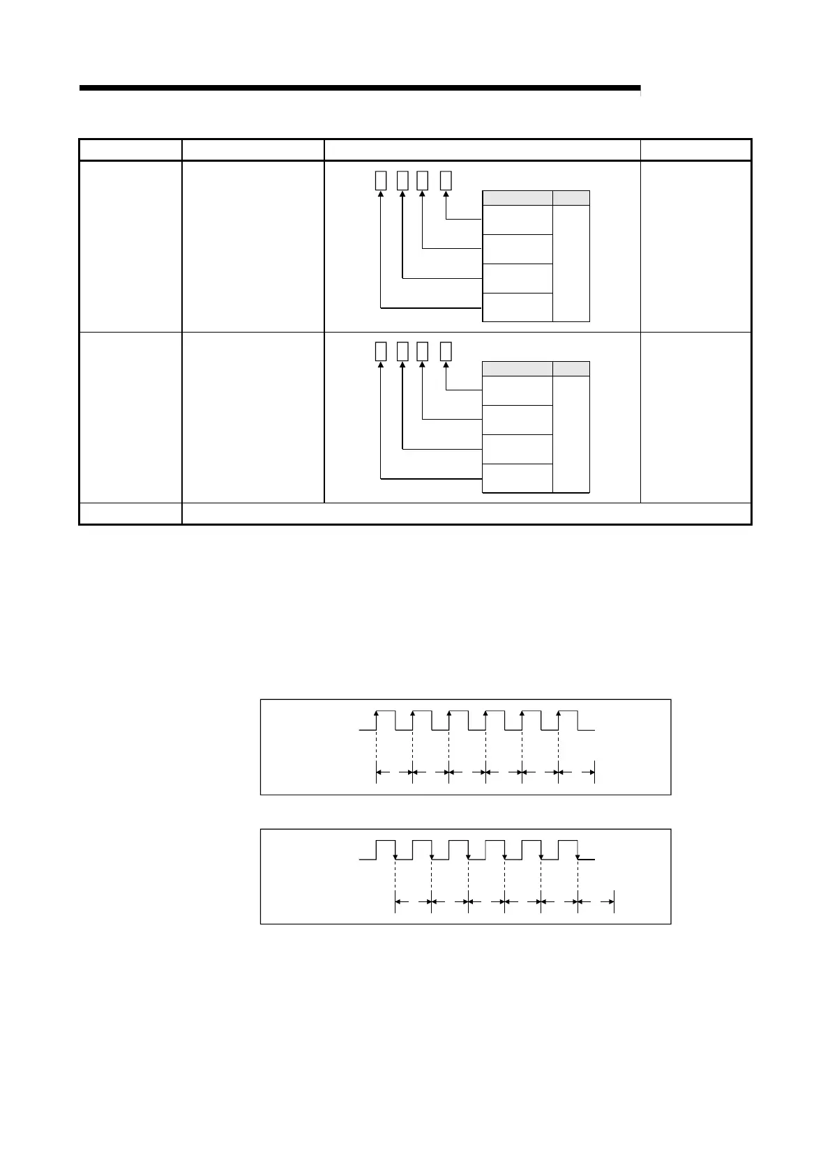
Switch 3
Input filter setting
(CH1 to CH4)
CH1 Input filter
0:30kpps
1:10kpps
2:1kpps
3:100pps
4:50pps
5:10pps
6:1pps
7:0.1pps
CH2 Input filter
CH3 Input filter
CH4 Input filter
H
Setting items
Meaning
0000H
Switch 4
Input filter setting
(CH5 to CH8)
CH5 Input filter
0:30kpps
1:10kpps
2:1kpps
3:100pps
4:50pps
5:10pps
6:1pps
7:0.1pps
CH6 Input filter
CH7 Input filter
CH8 Input filter
H
Setting items Meaning
0000H
Switch 5 Vacant
(1) Input voltage selection (Switch 1: lower 8 bits)
Set the level of the input signal on each channel.
(2) Pulse edge selection (Switch 2: lower 8 bits)
Set the pulse edge (rise edge/fall edge) on each channel.
For pulse edge selection, the differences between the rise edge and fall edge
and the count timings are shown below.
1) Rise edge
Count number
Pulse input
1 2 3 4 5 6
2) Fall edge
Pulse input
Count number
1 2 3 4 5 6
(3) Linear counter or Ring counter selection (Switch 2: upper 8 bits)
Set the count type (linear counter or ring counter) on each channel. (Refer to
Section 5.2.)
(4) Input filter setting (Switch 3, Switch 4)
Set the input pulse counting speed (maximum) on each channel. (Refer to
Section 3.1.)
 Loading...