10 - 1 10 - 1
MELSEC-Q
10 JOG OPERATION
CHAPTER 10 JOG OPERATION
This chapter details the JOG operation of the QD70.
10.1 Outline of JOG operation
Important
When performing JOG operation near the moving range, provide a safety circuit
externally.
If an external safety circuit is not provided, the workpiece may exceed the
moving range, causing accidents.
"JOG operation" is a control method to move a workpiece by only desired movement
amount, without using the positioning data (the pulse is kept output while the JOG start
signal is ON). It is used to move the workpiece to within the software stroke limit range
if operation has been stopped by the positioning control system connection
confirmation or by the software stroke limit function.
JOG operation
In JOG operation, turning ON the JOG start signal [Y18 to Y1F] outputs pulses from
the QD70 to the drive unit while it is ON to move the workpiece in the direction set in
"
JOG. 4
JOG direction flag".
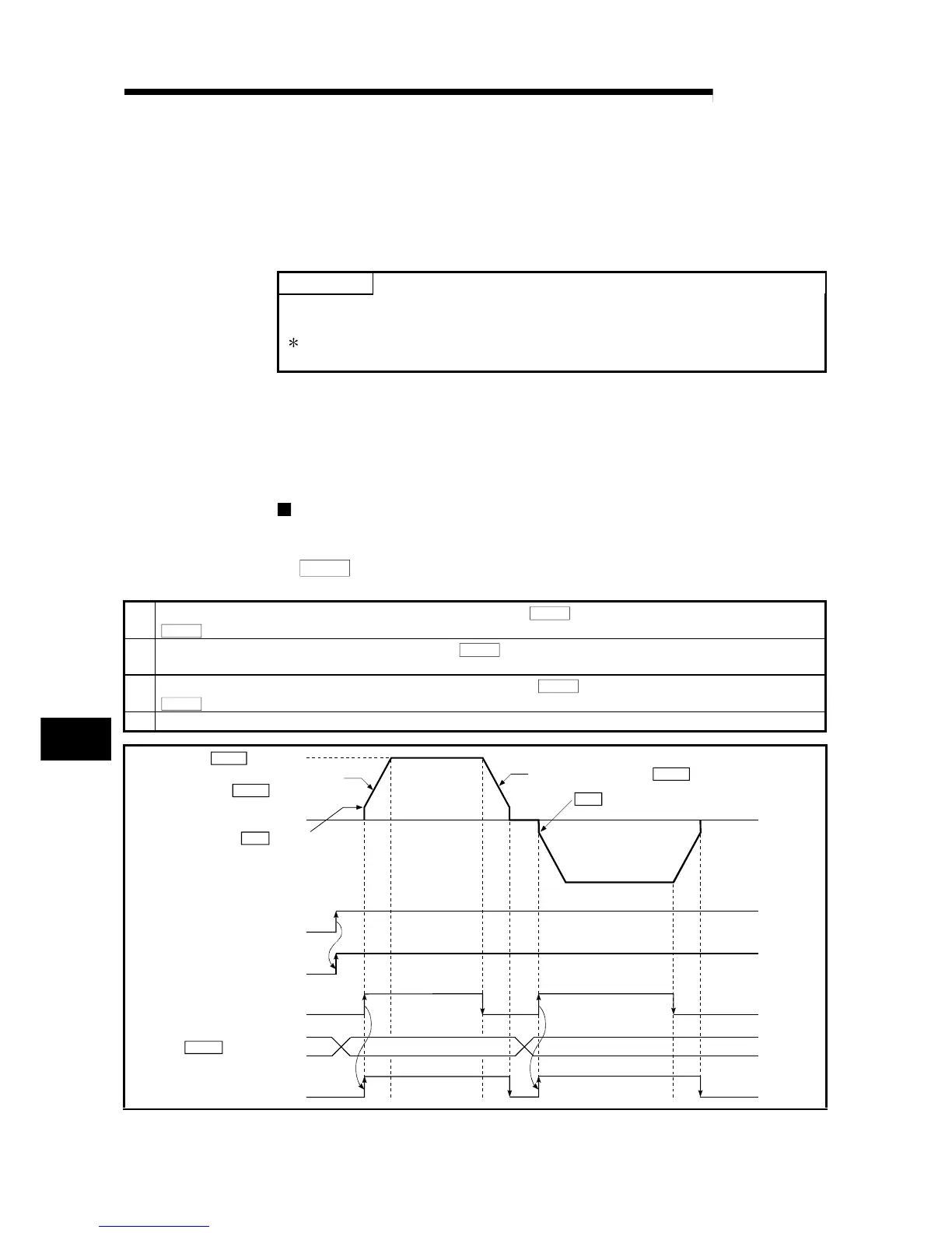
The following is an example of JOG operation.
1)
Turning ON the JOG start signal starts acceleration in the direction set in "
JOG. 4
JOG direction flag" at the acceleration time set in
"
JOG. 2
JOG ACC time". At this time, the BUSY signal turns from OFF to ON.
2)
When the accelerating workpiece reaches the speed set in "
JOG. 1
JOG speed", the workpiece continues moving at this speed.
(The workpiece moves at constant speed at 2) to 3).)
3)
Turning OFF the JOG start signal starts deceleration from the speed set in "
JOG. 1
JOG speed" at the deceleration time set in
"
JOG. 3
JOG DEC time".
4) When the speed falls to 0, the workpiece stops. At this time, the BUSY signal turns from ON to OFF.
JOG. 4
OFF
ON
OFF
ON
OFF
ON
ON
OFF
JOG. 1
JOG. 2
JOG. 3
1)
Pr. 6
Pr. 6
2) 3) 4)
JOG speed
Acceleration according to
" JOG ACC time"
Bias speed at start
Forward run JOG
operation
Deceleration according to " JOG DEC time"
Bias speed at start
Reverse run JOG operation
PLC READY
signal [Y0]
Module READY
signal [X0]
JOG start signal
[Y18 to Y1F]
JOG direction flag
BUSY signal
[X8 to XF]
0 : Forward run JOG
1 : Reverse run JOG
Fig. 10.1 JOG operation starting timing chart
10
 Loading...