3 - 11 3 - 11
MELSEC-Q
3 SPECIFICATIONS AND FUNCTIONS
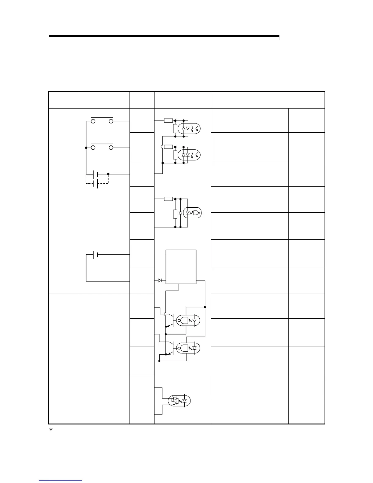
3.4.4 Input/output interface internal circuit
Shows summary image of the internal circuit of the interface for connection to external
devices of the QD70. (For QD70P4, axis 1).
Input/output
class
External wiring Pin No. Internal circuit Signal name
B9 Near-point dog signal DOG1
B11 Speed-position switching signal CHG1
B8 Common COM1-2
B17 Zero signal PG01
B18 Zero signal common PG01 COM
A1 External power input (0V) 24G
Input
24VDC
24VDC
*
B1 External power input (24VDC) +24V
B4 Pulse output F (CW/PULSE) PULSE F1
B2
Pulse output R
(CCW/SIGN)
PULSE R1
B3 Pulse output common PULSE COM1
B13 Deviation counter clear CLEAR1
Output
B14
D/D
converter
circuit
Deviation counter clear common CLEAR1 COM
: Either polarity can be connected to the common (COM1-2).
 Loading...