3 - 9 3 - 9
MELSEC-Q
3 SPECIFICATIONS AND FUNCTIONS
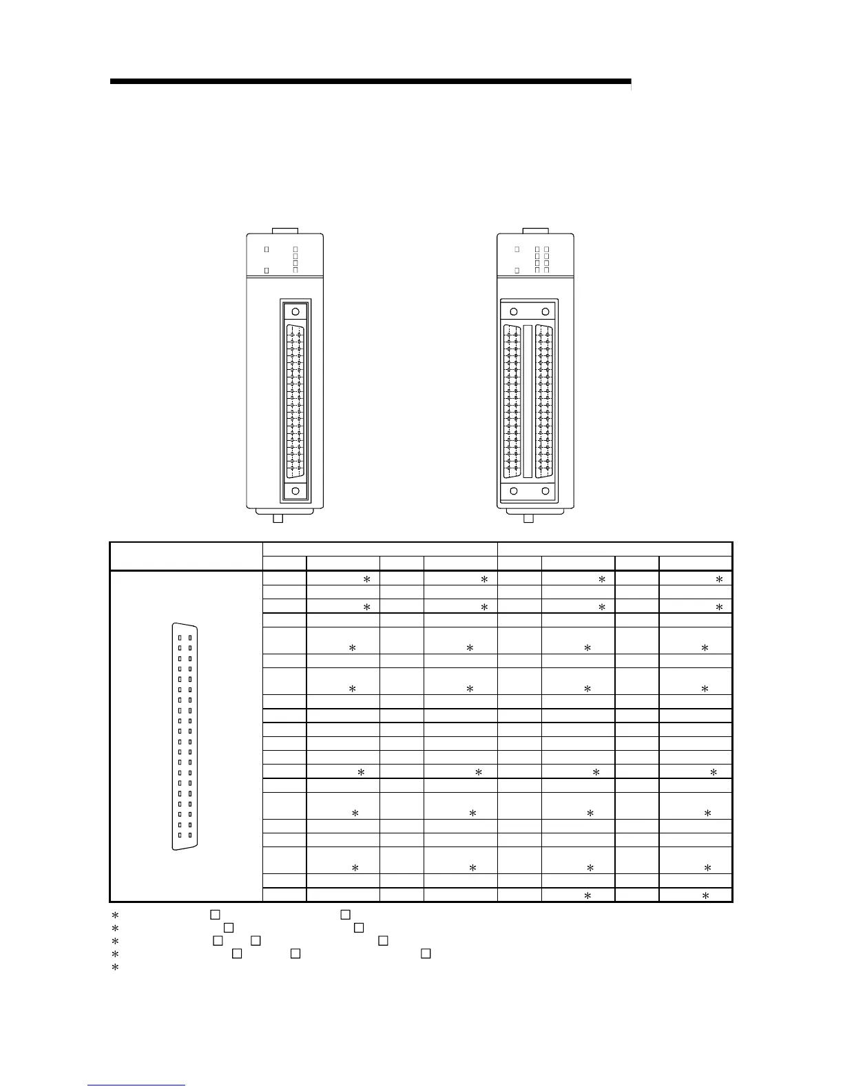
3.4.2 Signal layout for external device connection connector
The specifications of the connector section, which is the input/output interface for the
QD70 and external device, are shown below.
The signal layout for the QD70 external device connection connector is shown.
QD70P4
CON1
RUN
ERR.
AX2
AX1
AX4
AX3
QD70P4
QD70P8
CON2
RUN
ERR.
AX6
AX5
AX8
AX7
CON1
AX2
AX1
AX4
AX3
QD70P8
CON 2 (for Axes 5 to 8) CON 1 (for Axes 1 to 4)
Pin layout
Pin No. Signal name Pin No. Signal name Pin No. Signal name Pin No. Signal name
B20 PG06 COM 1 A20 PG08 COM 1 B20 PG02 COM 1 A20 PG04 COM 1
B19 PG06 A19 PG08 B19 PG02 A19 PG04
B18 PG05 COM 1 A18 PG07 COM 1 B18 PG01 COM 1 A18 PG03 COM 1
B17 PG05 A17 PG07 B17 PG01 A17 PG03
B16
CLEAR6
COM
2
A16
CLEAR8
COM 2
B16
CLEAR2
COM 2
A16
CLEAR4
COM 2
B15 CLEAR6 A15 CLEAR8 B15 CLEAR2 A15 CLEAR4
B14
CLEAR5
COM
2
A14
CLEAR7
COM
2
B14
CLEAR1
COM
2
A14
CLEAR3
COM
2
B13 CLEAR5 A13 CLEAR7 B13 CLEAR1 A13 CLEAR3
B12 CHG6 A12 CHG8 B12 CHG2 A12 CHG4
B11 CHG5 A11 CHG7 B11 CHG1 A11 CHG3
B10 DOG6 A10 DOG8 B10 DOG2 A10 DOG4
B9 DOG5 A9 DOG7 B9 DOG1 A9 DOG3
B8 COM 5-6 3A8COM 7-83B8COM 1-23A8COM 3-43
B7 PULSE F6 A7 PULSE F8 B7 PULSE F2 A7 PULSE F4
B6
PULSE
COM6
4
A6
PULSE
COM8
4
B6
PULSE
COM2
4
A6
PULSE
COM4
4
B5 PULSE R6 A5 PULSE R8 B5 PULSE R2 A5 PULSE R4
B4 PULSE F5 A4 PULSE F7 B4 PULSE F1 A4 PULSE F3
B3
PULSE
COM5
4
A3
PULSE
COM7 4
B3
PULSE
COM1 4
A3
PULSE
COM3 4
B2 PULSE R5 A2 PULSE R7 B2 PULSE R1 A2 PULSE R3
B20
B19
B18
B17
B16
B15
B14
B13
B12
B11
B10
B9
B8
B7
B6
B5
B4
B3
B2
B1
A20
A19
A18
A17
A16
A15
A14
A13
A12
A11
A10
A9
A8
A7
A6
A5
A4
A3
A2
A1
B1 Vacant A1 Vacant B1 +24V 5 A1 +24G 5
1: Common for PG0 . (Axis No. 1 to 8 goes into ).
2: Common for CLEAR . (Axis No. 1 to 8 goes into ).
3: Common for DOG , CHG .(Axis No. 1 to 8 goes into ).
4: Common for PULSE F , PULSE R . (Axis No. 1 to 8 goes into ).
5: The external power source (24VDC) should be connected in order to output a command pulse.
(When outputing a command pulse of axis 5 to 8, the external power source (24VDC) should be connected to A1 and B1 of the
connector CON1 (for axis 1 to 4 use).)
 Loading...