2 - 1 2 - 1
MELSEC-Q
2 SYSTEM CONFIGURATION
CHAPTER 2 SYSTEM CONFIGURATION
This chapter explains the system configuration of the QD70.
2.1 General image of system
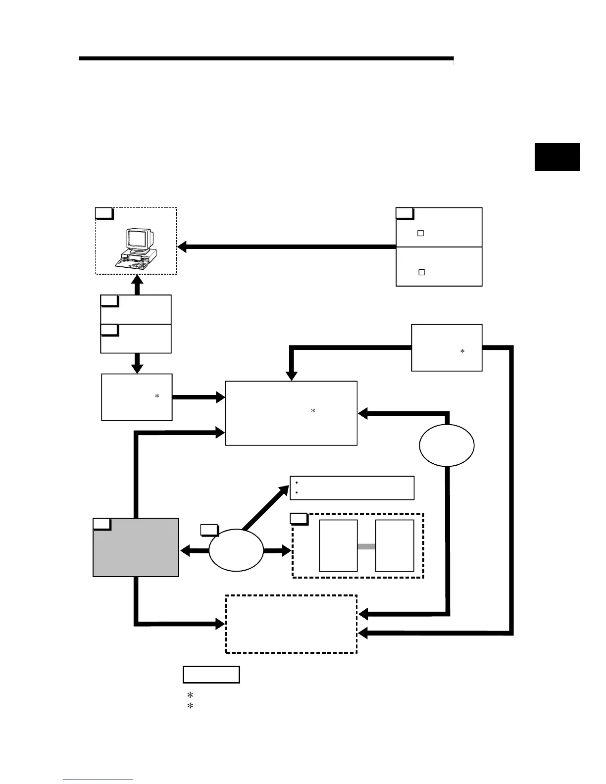
The following is the general configuration including the QD70, PLC CPU, peripheral
device and others.
(The numbers in the sketch correspond to the "Nos." in the table in "Section 2.2
Component list" on the next page.)
Extension system
6
Drive
unit
Motor
4
5
RS-232
cable
USB cable
1
Positioning module
QD70P4/QD70P8
7
Connection
cable
Mechanical system inputs (switches)
Near-point dog signal
Speed-position switching signal
Extension
cable
Power supply
module
Main base unit
CPU module
3 2
GX Developer
(SW D5C-GPPW-E)
GX Configurator-PT
(SW D5C-QPTU-E)
Peripheral device
Personal
computer
1
2
2
REMARK
1: For the usable CPU module, refer to "Section 2.3 Applicable system".
2: For the usable base unit and power supply module, refer to the CPU Module
User's Manual.
2
 Loading...