3 - 10 3 - 10
MELSEC-Q
3 SPECIFICATIONS AND FUNCTIONS
3.4.3 List of input/output signal details
The details of each QD70 external device connection connector are shown below:
Signal name Pin No. Symbol
Signal details
(Negative logic is selected by I/O signal logic selection)
Near-point dog signal
A10
A9
B10
B9
DOG
•
This signal is used for detecting the near-point dog during OPR control.
•
The near-point dog OFF ON is detected at the rising edge.
•
The near-point dog ON
OFF is detected at the falling edge.
Speed-position switching signal
A12
A11
B12
B11
CHG
•
This signal is input as a control switching signal in speed-position switching
control.
Common A8 B8 COM
•
Common for near-point dog signal and speed-position switching control
signal.
Zero signal
A19
A17
B19
B17
PGO
•
Input the zero signal for OPR control.
Use the pulse encoder's zero signal and so on.
•
Also use this signal when the OPR method is the stopper method and the
OPR complete is input from an external source.
•
The OP is detected at the falling edge.
Zero signal common
A20
A18
B20
B18
PGO COM
•
Common for zero signal.
External power input (0V) A1 (COM1) 24G
External power input (+24V) B1 (COM1) +24V
•
These signals are used to input 24VDC power for driving the pulse output
circuit. (Common to all axes)
Pulse output F
A7
A4
B7
B4
PULSE F
•
This signal is used to output command pulses to the open collector
compatible drive unit.
CW/CCW mode: CW, PULSE/SIGN mode: PULSE
Pulse output R
A5
A2
B5
B2
PULSE R
•
This signal is used to output command pulses to the open collector
compatible drive unit.
CW/CCW mode: CCW, PULSE/SIGN mode: SIGN
Pulse output common
A6
A3
B6
B3
PULSE
COM
•
Common for pulse output F and pulse output R.
Deviation counter clear
A15
A13
B15
B13
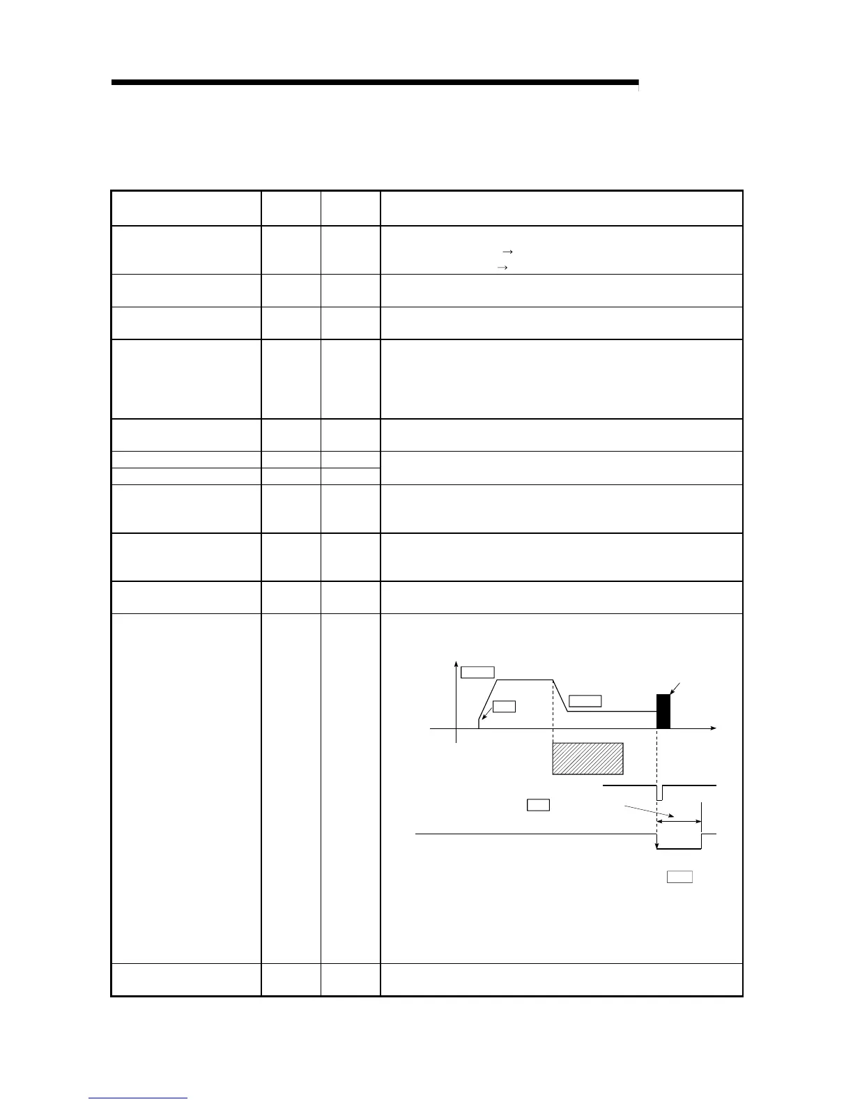
CLEAR
•
This signal is output during machine OPR control.
(Example) When carry out OPR control with stopper
2
.
CLEAR
OPR. 4
OPR. 5
Pr. 8
Pr. 6 Bias
speed at star
t
Speed
OPR speed
Creep speed
Stopper
Near-point dog
Deviation counter
clear signal output time
Time
After feed pulse output stops
Zero signal
•
The output time of the deviation counter clear signal is set in "
Pr. 8
Deviation
counter clear signal output time".
•
Use the drive unit that can reset the droop pulse amount in the internal
deviation counter when the QD70 turns this signal ON.
(Note) The deviation counter clear is a signal output by the QD70 during
machine OPR control. It cannot be output randomly.
Deviation counter clear common
A16
A14
B16
B14
CLEAR
COM
•
Common for deviation counter clear
 Loading...