Chapter Three: Overview General Information
33
Chapter Three: Overview
General Information
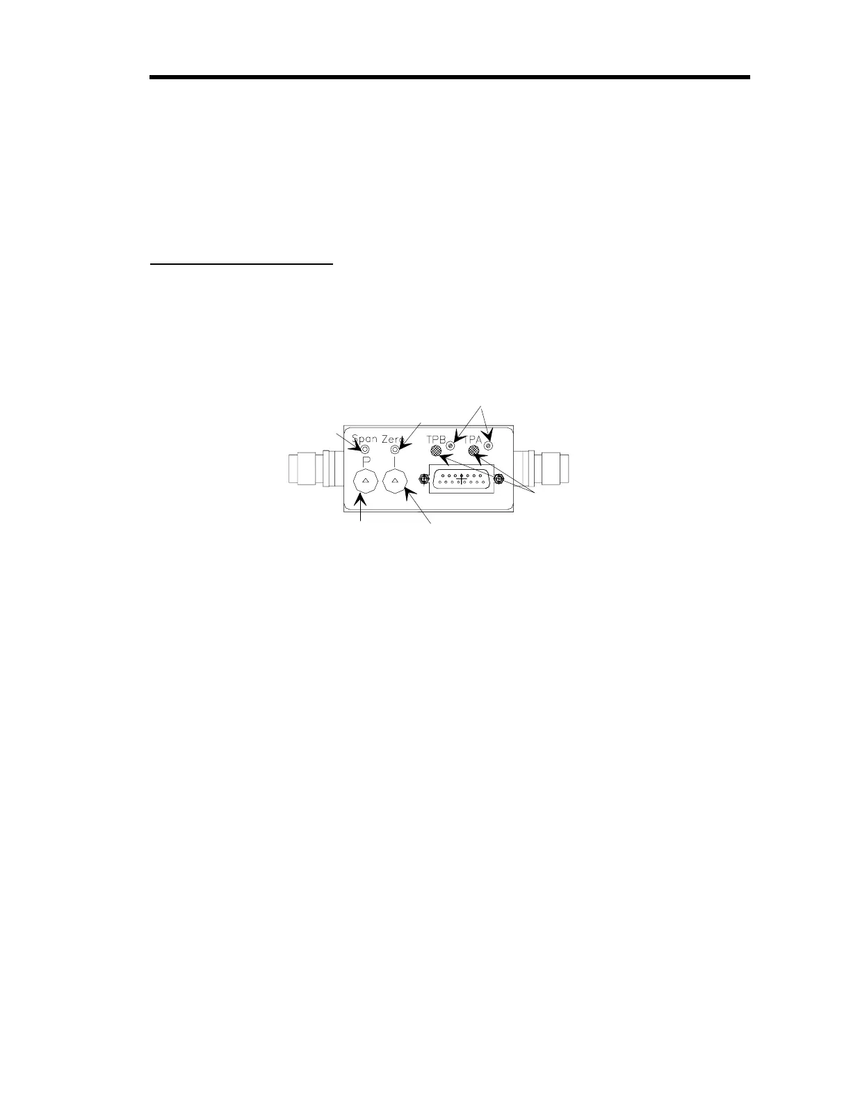
Figure 13 shows the top view of the 640 Series Pressure Controller. The user adjustable controls
for zero, span, the P term, the I term, and the trip points are located on the top of the controller.
The trip point settings can be measured through two test jacks, located on the side of unit, as
shown in Figure 4, page 18.
Span
Pot
Zero Pot
Trip Point
Adjustments
Proportional
Adjustment
Inte
ral
Adjustment
Trip Point
Status LEDs
Figure 13: Top View of the 640 Series Controller
Pressure Control Range
The 640 Series controller can control pressure over a range of 2% to 100% of full scale. This
means that a 640 controller with a 1000 Torr transducer can control pressure from 20 to 1000
Torr, and a unit with a 100 Torr transducer can control pressure from 2 to 100 Torr.