How To Check the Zero Cha
ter Four: O
eration
44
To properly zero a 640 controller (that contains an absolute transducer):
1.
Install the 640 controller in a system and connect a power supply/readout.
The pressure signal is available on pin 2 of the I/O connector. Use either pin 11 or 12 as
the ground. Refer to Table 3, page 13, for the pinout of the I/O connector.
2.
Pump the system down to a pressure below the resolution of the transducer within the
640 controller. Table 9 lists the recommended pressure levels.
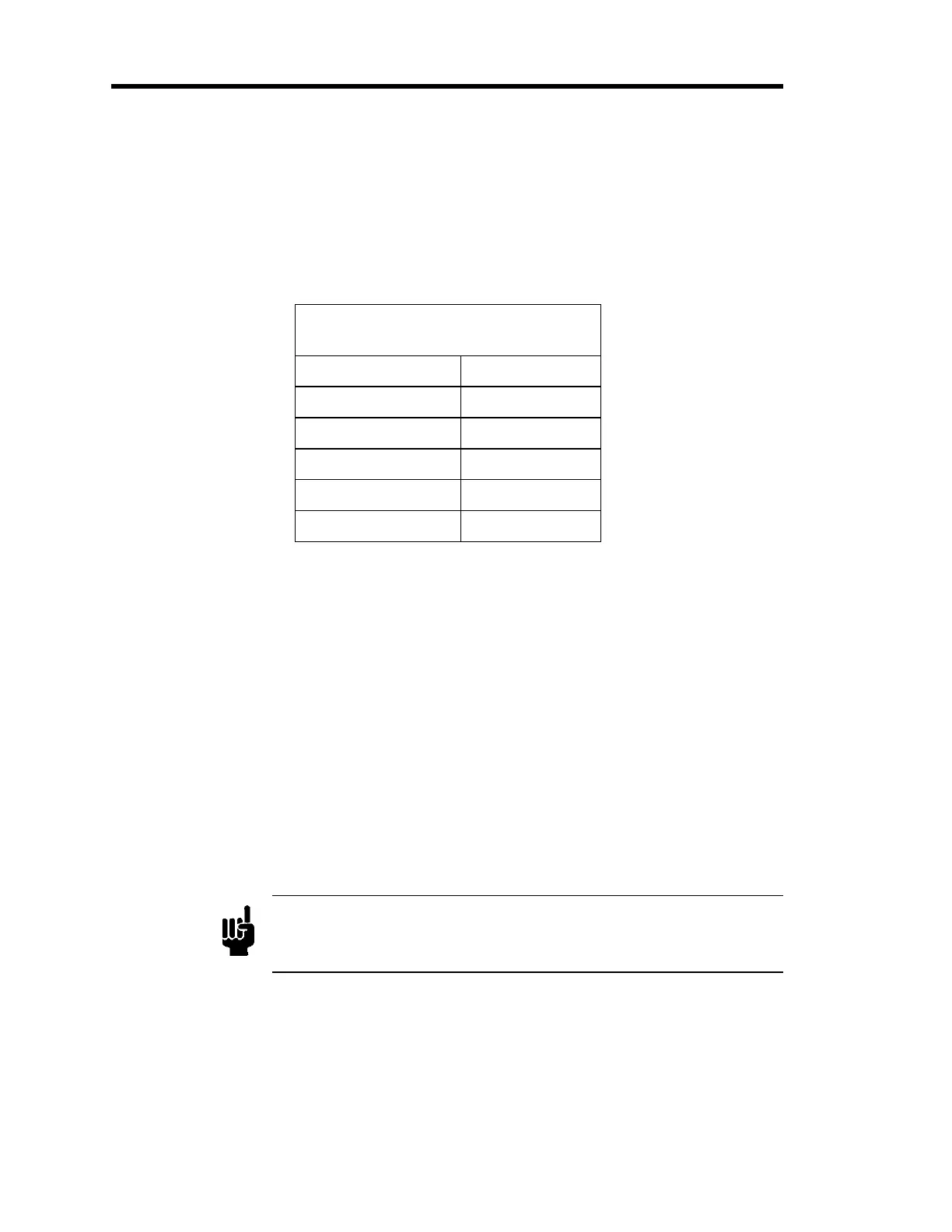
Highest Pressure for Zero Adjustment
of an Absolute Transducer
Full Scale Range Pressure
10 Torr < 5 x 10
-4
Torr
100 Torr < 5 x 10
-3
Torr
1000 Torr < 5 x 10
-2
Torr
60 psia < 2 x 10
-3
psia
100 psia < 5 x 10
-3
psia
Table 9: Highest Suggested Pressure for Zero Adjustment of an Absolute Transducer
3.
Using a small screwdriver, adjust the
ZERO
pot until the readout displays zero (0000).
Refer to Figure 13, page 33, for the location of the
ZERO
pot.
How To Zero a Type 641 (Gage) Unit
Follow the instructions below to zero a 641 controller (that contains a gage pressure transducer).
1.
Install the 641 controller in a system with a power supply/readout.
The pressure signal is available on pin 2 of the I/O connector. Use either pin 11 or 12 as
the ground. Refer to Table 3, page 13, for the pinout of the I/O connector.
2.
Open the process port to local atmospheric pressure.
Note
The “reference” port of the transducer is always open to the local
atmospheric conditions. The zero is set only when the “Controlled
Pressure Port” is also open to local atmospheric pressure.
3.
Using a small screwdriver, adjust the
ZERO
pot until the readout displays zero (0000).
Refer to Figure 13, page 33, for the location of the
ZERO
pot.



 To Next Page