Chapter Four: Operation How To Select the Tri
Point Action
47
How To Select the Trip Point Action
The 640 Series controller is initially configured with TP A set to trip high (it is on when the
pressure is
above
the trip point pressure) and TP B set to trip low (it is on when the pressure is
below
the trip point pressure). To change the action of the trip points you must remove the cover
of the units and change jumpers on the Transducer board. Each trip point has a jumper block
with the jumper positions labeled TL (trip low) and TH (trip high).
1.
Stop the gas flow through the 640 Series controller.
2.
Remove any leads or wires attached to the connector on the 640 Series controller.
3.
Use a
3
/
16
” hex wrench (or open-ended wrench) to remove the hex nuts on each side of
the I/O connector.
Refer to Figure 1, page 13, for the location of the hex nuts on the I/O connector. Place
the hex nuts aside for safe keeping.
4.
Position the controller with the front side facing you, and pull up on the enclosure to
remove it.
The board assembly will be visible, with the Transducer board facing you and the
Control board behind it.
5.
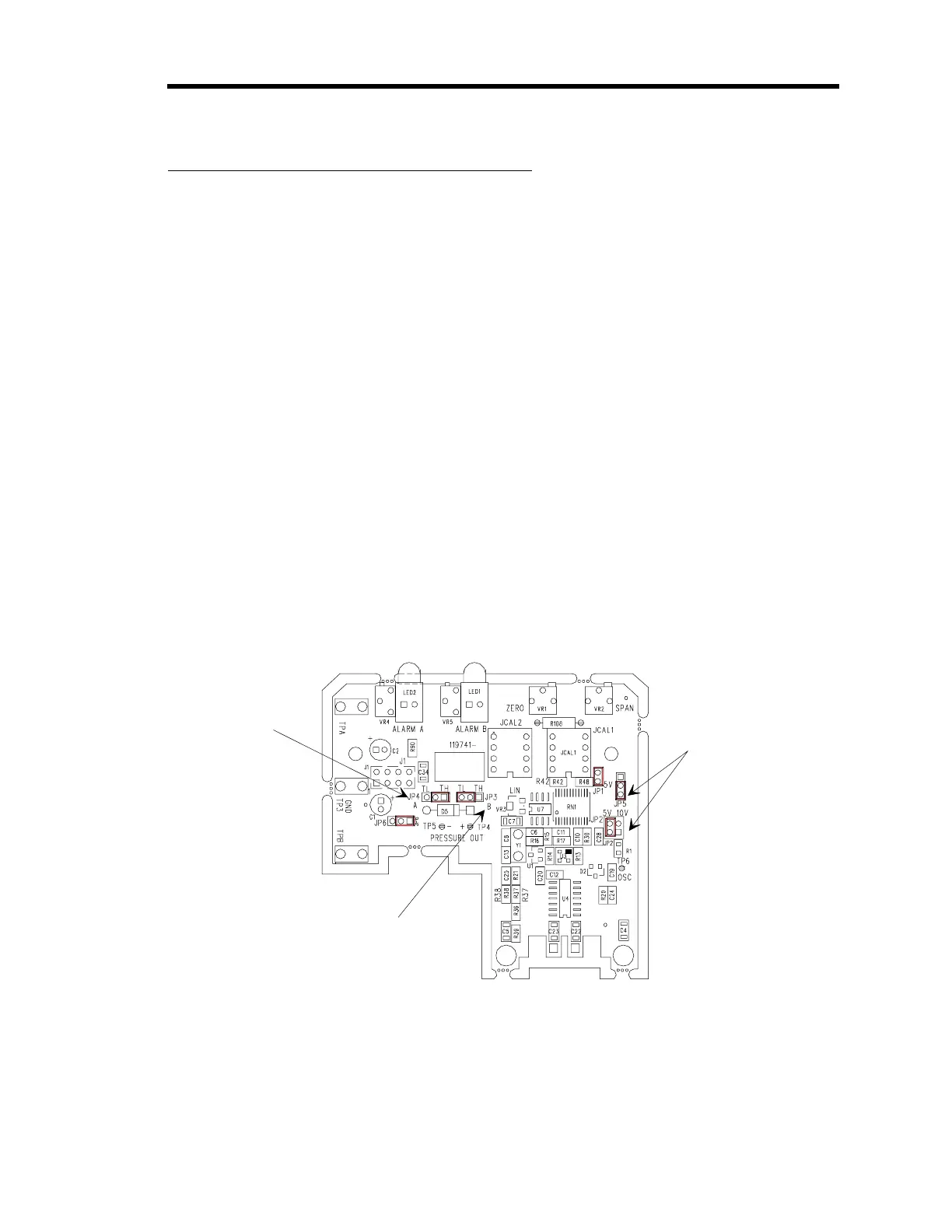
Locate the jumper blocks labeled “JP4” and “JP3” in the middle of the Transducer board.
Refer to Figure 21 for the location of the jumper blocks.
JP4 Jumper Block
sets TPA action
JP3 Jumper Block
sets TPB action
Jumpers Block JP1 and JP2
determine the ran
e of the
pressure output si
nal
Figure 21: Jumper Positions on the Transducer Board
6.
Position the jumper on jumper block “JP4” to select the action for TP A.
Jumper block “JP3” controls TP B.



 To Next Page