Chapter Four: Operation How To Select U
stream Control
51
How To Select Upstream Control
The 640 Series controller is configured for downstream control when it leaves the factory. To
use it in a upstream control application, you must remove the enclosure cover and reposition two
jumpers on the Control board.
1.
Stop the gas flow through the 640 Series controller.
2.
Remove I/O cables attached to the connector on the 640 Series controller.
3.
Use a
3
/
16
” hex wrench (or open-ended wrench) to remove the hex nuts on each side of
the I/O connector.
Refer to Figure 3, page 17, for the location of the hex nuts on the I/O connector. Place
the hex nuts aside for safe keeping.
4.
Position the controller with the back side facing you, and pull up on the enclosure to
remove it.
The back side of the unit lists the I/O connector pinout. The board assembly will be
visible, with the back of the Control board facing you. The Transducer board is
connected to the front of the Control board.
5.
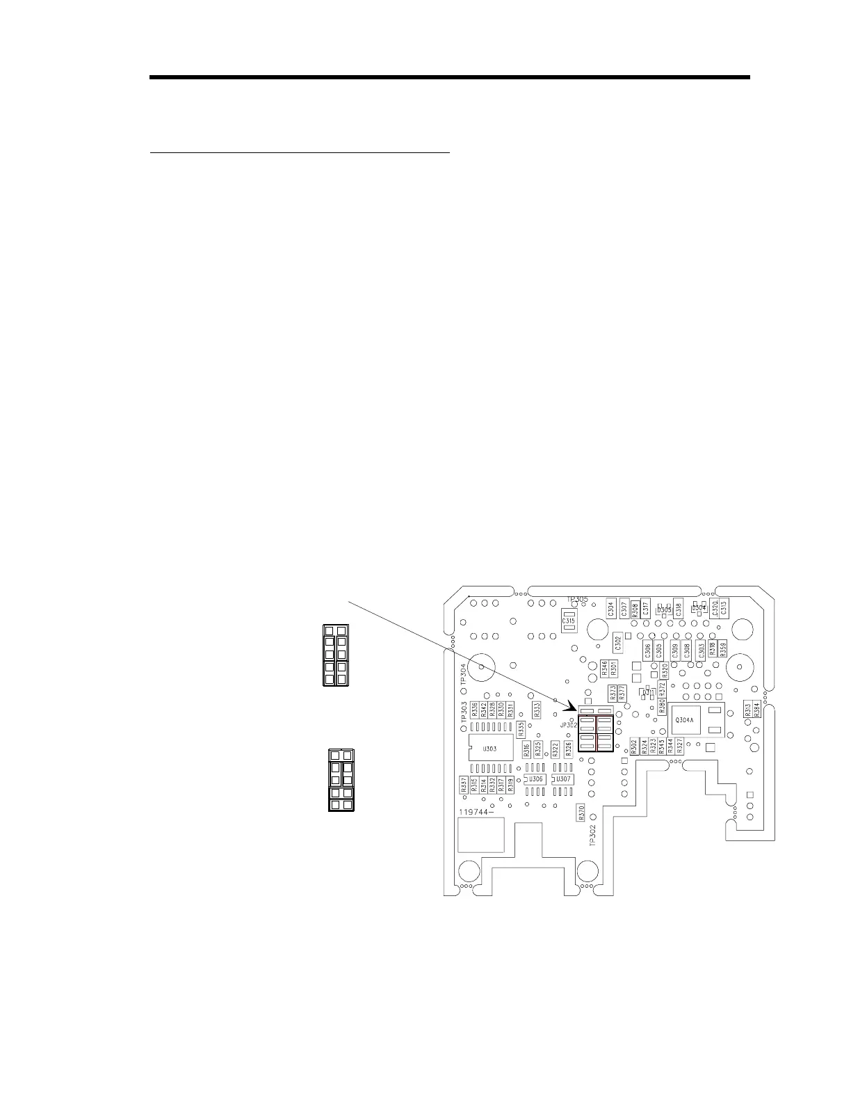
Locate the jumper block labeled “JP302” in the middle section of the Control board.
Refer to Figure 22 for the location of the jumper block.
Jumper JP302 for Upstream
or Downstream Control
{
Jumpers positioned
for Downstream control
(factory default). Shown
with a normally closed valve.
Jumpers positioned for
Upstream control. Shown
with a normally closed valve.
{
Note:
Do not place a jumper
on the top pins which would
cause the pins to short out.
Figure 22: Jumper Positions on the Control Board
6.
Position the lower two jumpers horizontally for upstream control.