Appendix B: Valve Orifice Selection General Information
57
Appendix B: Valve Orifice Selection
General Information
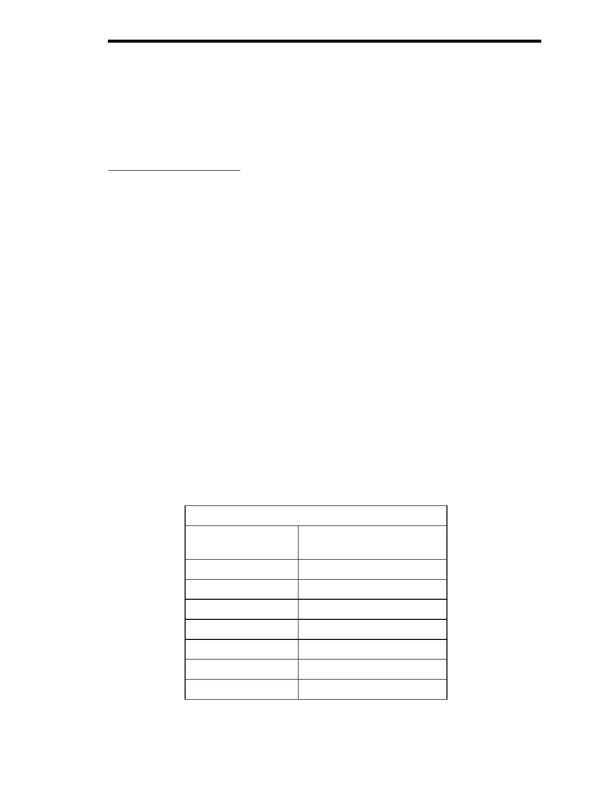
The 640 controller is available in six valve orifice sizes. You should confirm that the valve
orifice in your 640 controller is the correct size for your application before you install it into your
system. The orifice is
not
adjustable and is only replaceable at the factory.
This selection guide is valid with either seal material (metal or elastomer).
Checking the Orifice Size
The orifice number is included in the model code number of your 640 controller, as shown in
Figure 23. The nominal flow rate range for the orifice numbers are listed in Table 10. Refer to
Appendix D: Model Code Explanation,
page 67, for a complete description of the model code.
Model Code: 640AXXXYZQRST
where XXX = Pressure Range
Y = Fitting Type
Z = Valve Type
Q = Body Seal Material
R = Valve Orifice Size (Flow Range)
S = Trip Points
T = Valve Plug Material
Figure 23: Model Code Explanation
Orifice Size
Orifice Size
(Model Code Entry)
Nominal Range
(sccm of N
2
with 1 ATM ∆P)
A50
1 200
2 1000
3 5000
4 10000
5 20000
6 50000
Table 10: Orifice Size