www.mobotix.com • sales@mobotix.com
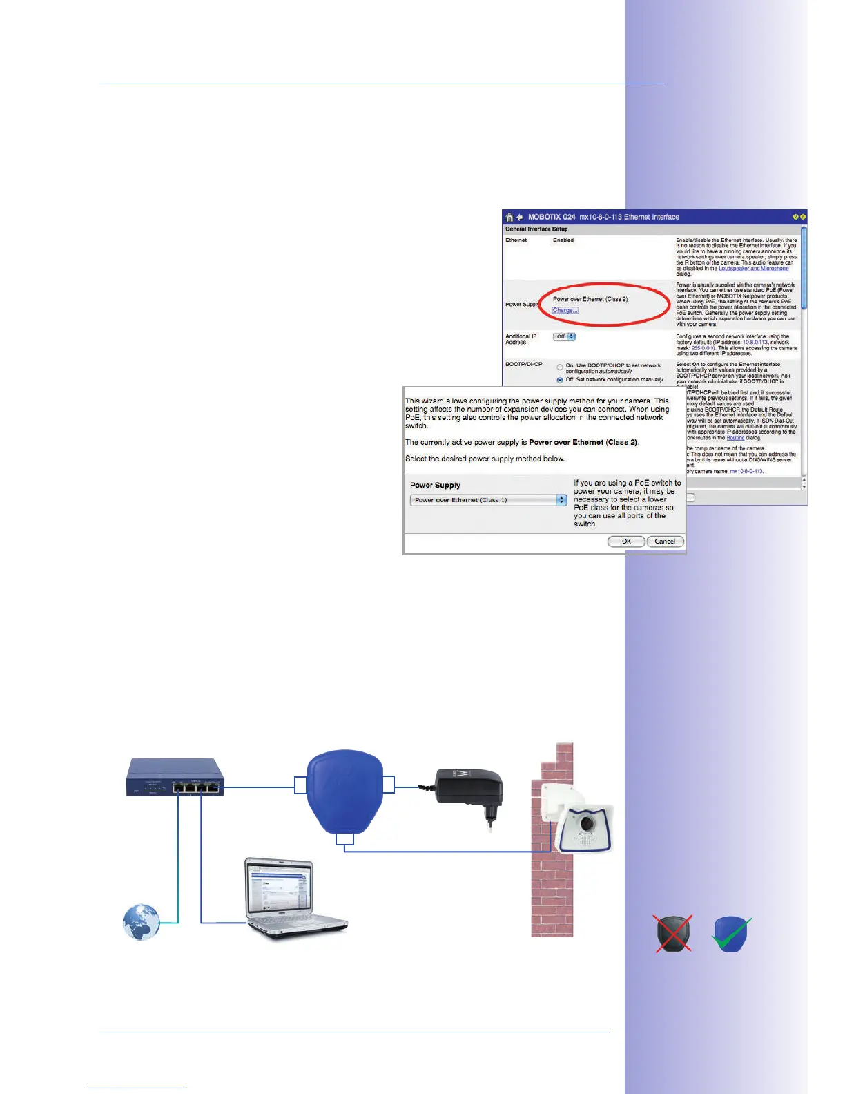
. This default is usually fine and nothing needs
to be changed. However, if the lower power level class 1 is sucient for your application,
it may – due to possible internal power distribution schemes amongst the ports of the PoE
switch in use – be advantageous to change the PoE power level class in the browser:
1. Select
(for experts).
2. Under , click .
3. A will appear to guide you through the PoE
configuration steps.
4. The camera will then need to be restarted via a hard reboot:
Disconnect the camera from the power supply, then reconnect
it, for example, by disconnecting and then reconnecting the
network cable at the PoE switch.
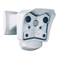
1. Connect the factory pre-installed cable of the camera to the Camera connector of
the PoE adapter.
2. Connect the connector of the PoE adapter to the Ethernet connector
of the switch/router or the Ethernet socket.
3. Plug the RJ45 connector of the power supply unit into the connector of
the PoE adapter.
Variable PoE: multiple
cameras can be oper-
ated simultaneously
from the same switch
For the M24M, you
should use the new
blue MX-NPA-PoE-Set
- previous MOBOTIX
network power acces-
sories such as the NPA
Set, Power Box and
Power Rack (MX-NPA-
Set, MX-NPR-4 and
MX-NPR8/20) are
not suitable for use
with the M24M
The IP addresses in
the diagram are shown
only as an example