NICE5000 User Manual 3 Mechanical and Electrical Installation
- 45 -
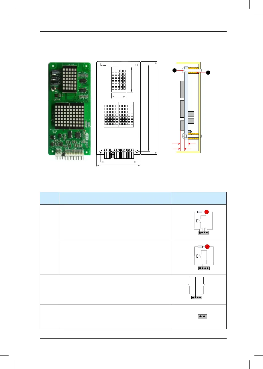
3.4.2 MCTC-HCB-R1 (Ultrathin Dot-Matrix Display Board)
Figure 3-6 Appearance, dimensions, and installation method of HCB-R1
4-Φ3.5
56.0
134.0
144.0
22
.8
39.0
CN1
J1
UP DOWNST XF
70
MCTC-HCB-R1
Unit: mm
6.7
10
MCTC-HCB
-R1
1
2
1 - Plastic support higher than 1 cm
2 - Self-tapping screw 4-φ4.9x30
The following table describes the input and output terminals.
Table 3-7 Input and output terminals of HCB-R1
Terminal
Name
Function Terminal Wiring
UP
Interface for the up call button and indicator
Pins 2 and 3 are for up call input. Pins 1 and 4 are power
supply for the up call indicator (24 VDC output, load
capacity: 40 mA).
1 2 3 4
Up call indicator
Up call
button
DOWN
Interface for the down call button and indicator
Pins 2 and 3 are for down call input. Pins 1 and 4 are
power supply for the down call indicator (24 VDC output,
load capacity: 40 mA).
1 2 3 4
Down call indicator
Down call
button
XF/ST
Interface for the re emergency and elevator lock
switches
Pins 1 and 2 are for elevator lock input. Pins 3 and 4 are
for re emergency input.
1 2 3 4
Fire
emergency
input
Elevator
lock
input
J1
Terminal for setting the oor address.
Short J1, and press the UP button or DOWN button to
set the oor address (range 0–56). After the jumper cap
is removed, the address is automatically stored.