NICE5000 User Manual 3 Mechanical and Electrical Installation
- 47 -
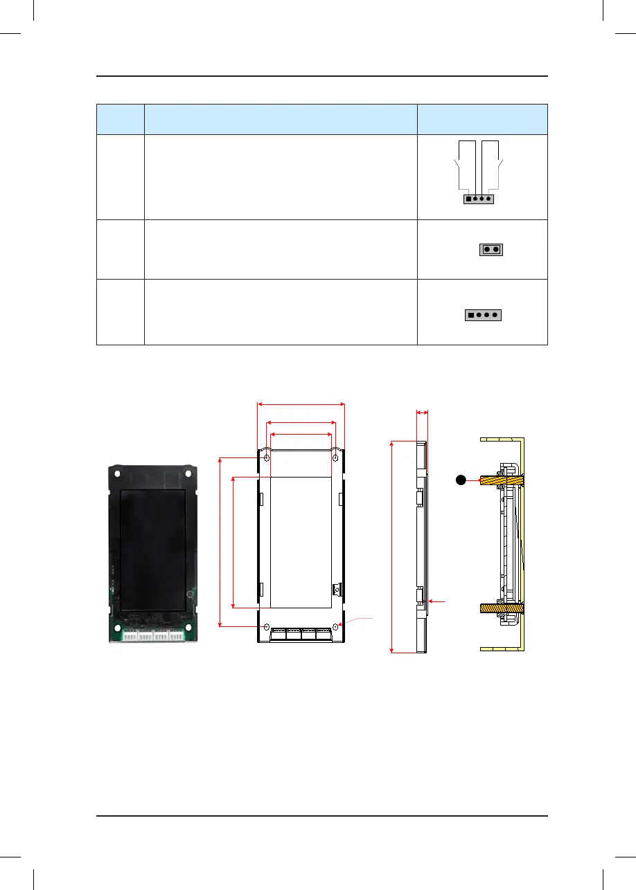
Terminal
Name
Function Terminal Wiring
XF/ST
Interface for the re emergency and elevator lock switch
Pins 1 and 2 are for elevator lock input. Pins 3 and 4 are
for re emergency input.
1 2 3 4
Fire
emergency
input
Elevator
lock input
J1
Terminal for setting the oor address
Short J1, and press the UP button or DOWN button to set
the oor address (range 0–56). After the jumper cap is
removed, the address is automatically stored.
CN1
Modbus communication and power supply terminal
Pins 2 and 3 are for Modbus communication.
Pins 1 and 4 are for power supply.
3.4.4 MCTC-HCB-D5 (Ultrathin Segment LCD Display Board)
Figure 3-8 Appearance, dimensions, and installation method of HCB-D5
9.3
76
60
53.5
118
91.5
136.5
4-φ4.5
JP2 CN1 JP1 JP3
1
MCTC-HCB-D5
1 - 4-M4x18 screw
MCTC
-HCB-D
5
1