3 Mechanical and Electrical Installation NICE5000 User Manual
- 48 -
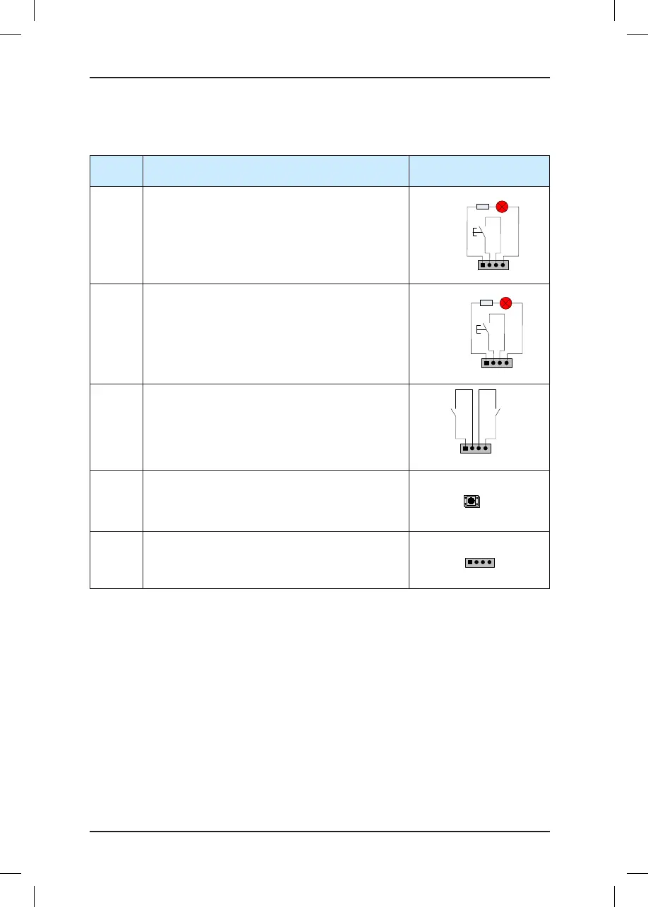
The following table describes the input and output terminals of HCB-D5.
Table 3-9 Input and output terminals of HCB-D5
Terminal
Name
Function Terminal Wiring
JP2
Interface for the up call button and indicator
Pins 2 and 3 are for up call input. Pins 1 and 4 are
power supply for the up call indicator (24 VDC output,
load capacity: 40 mA).
1 2 3 4
Up call indicator
Up call
button
JP3
Interface for the down call button and indicator
Pins 2 and 3 are for down call input. Pins 1 and 4
are power supply for the down call indicator (24 VDC
output, load capacity: 40 mA).
1 2 3 4
Down call indicator
Down call
button
JP1
Interface for the re emergency and elevator lock
switch
Pins 1 and 2 are for elevator lock input. Pins 3 and 4
are for re emergency input.
1 2 3 4
Fire
emergency
input
Elevator
lock input
S1
Button for setting the oor address.
Hold down the button to adjust the oor address (range
0–56). After you stop pressing, the address number
blinks three times and the setting is successful.
CN1
Modbus communication and power supply terminal.
Pins 2 and 3 are for Modbus communication.
Pins 1 and 4 are for power supply.