NICE5000 User Manual 3 Mechanical and Electrical Installation
- 49 -
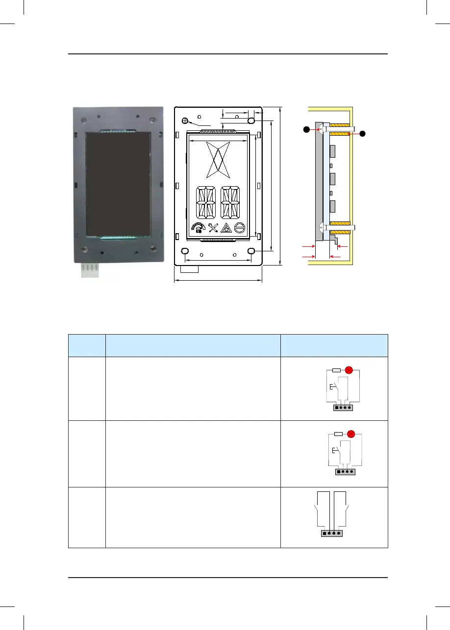
3.4.5 MCTC-HCB-U1 (4.3-inch Segment LCD Display Board)
Figure 3-9 Appearance, dimensions, and installation method of HCB-U1
3-5.5
3-4.5
Φ4.5
143.5
79.2
118.0
60.0
53.0
92.0
Unit: mm
9.4
15
Unit: mm
MCTC-HCB
-U1
1 - Plastic support higher than 1 cm
2 - Self-tapping screw 4-φ4.9x30
1
2
The following table describes the input and output terminals of HCB-U1.
Table 3-10 Input and output terminals of HCB-U1
Terminal
Name
Function Terminal Wiring
J1
Interface for the up call button and indicator
Pins 2 and 3 are for up call input. Pins 1 and 4
are power supply for the up call indicator (24 VDC
output, load capacity: 40 mA).
1 2 3 4
Up call indicator
Up call
button
J2
Interface for the down call button and indicator
Pins 2 and 3 are for down call input. Pins 1 and 4
are power supply for the down call indicator (24
VDC output, load capacity: 40 mA).
1 2 3 4
Down call indicator
Down call
button
J3
Interface for the re emergency and elevator lock
switches
Pins 1 and 2 are for elevator lock input. Pins 3 and
4 are for re emergency input.
1 2 3 4
Fire
emergency
input
Elevator
lock input