3 Mechanical and Electrical Installation NICE5000 User Manual
- 50 -
Terminal
Name
Function Terminal Wiring
S1
Button for setting the oor address.
Hold down the button to adjust the oor address
(range: 0−56). After you stop pressing, the address
number blinks three times, and therefore the setting
is successful.
CN1
Modbus communication and power supply terminal
Pins 2 and 3 are for Modbus communication. Pins 1
and 4 are for DC power supply.
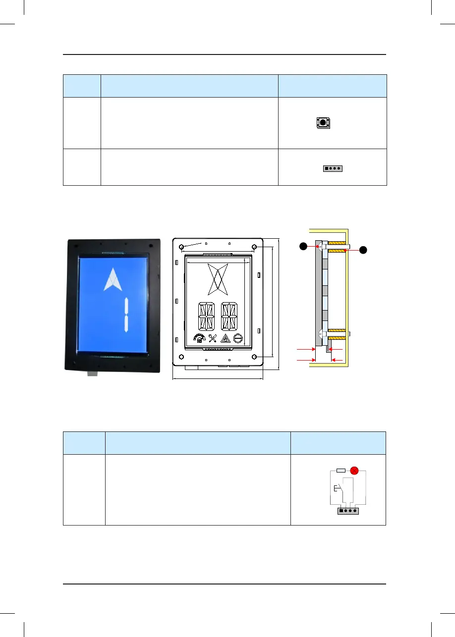
3.4.6 MCTC-HCB-V1 (6.4-inch Segment LCD Display Board)
Figure 3-10 Appearance, dimensions, and installation method of HCB-V1
184.6
131
160
105
95
135
Φ4
.
5
Unit: mm
17.9
14.2
2
MCTC-HCB-V1
1 - Plastic support higher than 1 cm
2 - Self-tapping screw 4-φ4.9x30
1
The following table describes the input and output terminals of HCB-V1.
Table 3-11 Input and output terminals of HCB-V1
Terminal
Name
Function Terminal Wiring
J1
Interface for the up call button and indicator
Pins 2 and 3 are for up call input. Pins 1 and 4 are
power supply for the up call indicator (24 VDC output,
load capacity: 40 mA).
1 2 3 4
Up call indicator
Up call
button