NICE5000 User Manual 3 Mechanical and Electrical Installation
- 51 -
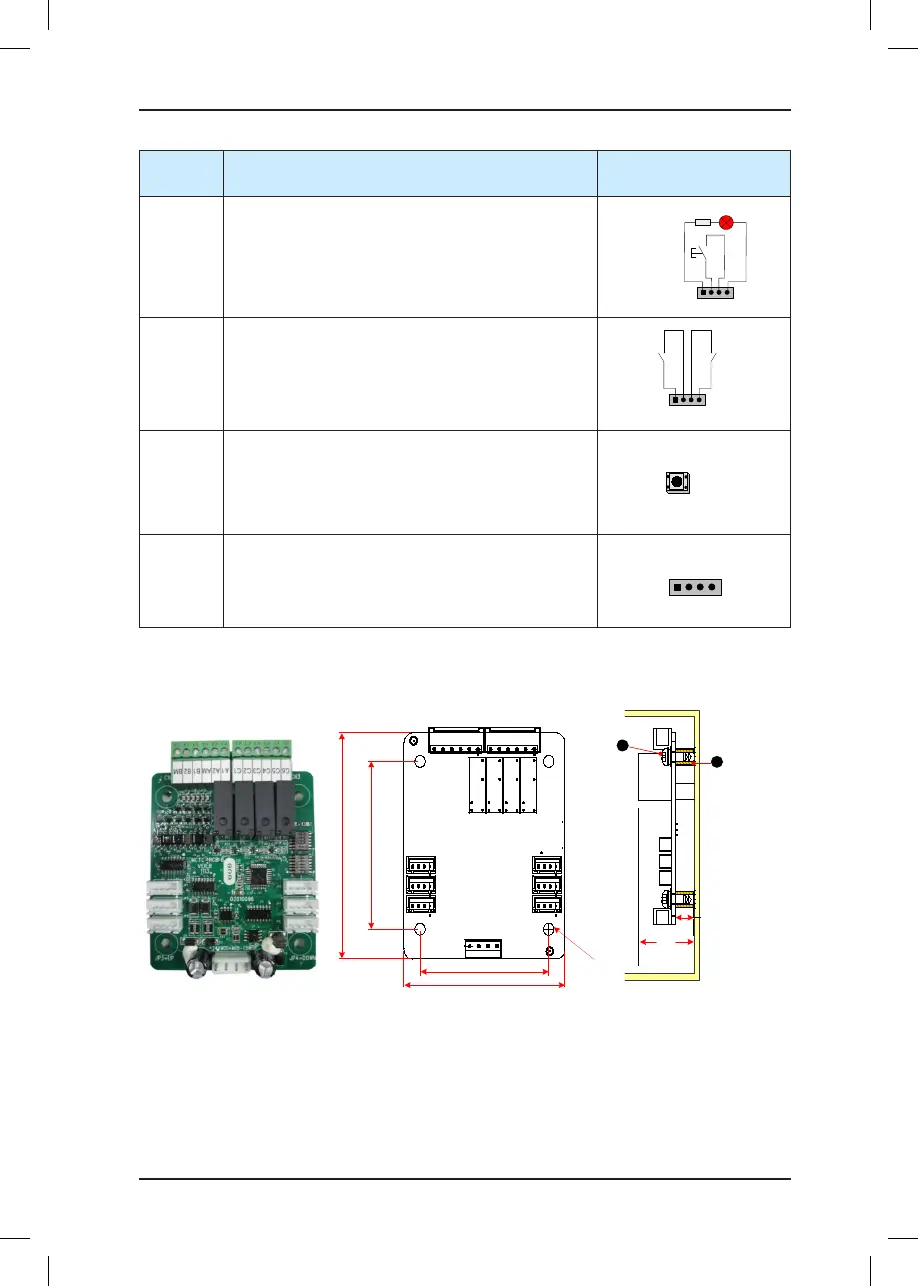
Terminal
Name
Function Terminal Wiring
J2
Interface for the down call button and indicator
Pins 2 and 3 are for down call input. Pins 1 and 4
are power supply for the down call indicator (24 VDC
output, load capacity: 40 mA).
1 2 3 4
Down call indicator
Down call
button
J3
Interface for the re emergency and elevator lock
switch
Pins 1 and 2 are for elevator lock input. Pins 3 and 4
are for re emergency input.
1 2 3 4
Fire
emergency
input
Elevator
lock
input
S1
Button for setting the oor address.
Hold down the button to adjust the oor address
(range: 0−56). After you stop pressing, the address
number blinks three times, and therefore the setting is
successful.
CN1
Modbus communication and power supply terminal
Pins 2 and 3 are for Modbus communication. Pins 1
and 4 are for DC power supply.
3.4.7 MCTC-HCB-B (No Display Hall Call Board)
Figure 3-11 Appearance, dimensions, and installation method of HCB-B
56.1
70.1
84.5
62.7
4-φ4.5
24V
MOD+
MOD-COM
JP5
JP3
JP1
JP6
JP4
JP2
CN2 CN3
K1 K2 K3 K4
JP3=UP JP4=DOWN
Unit: mm
MCTC-HCB-B
MCTC-HCB-B
8.8
26.4
1 - Plastic support higher than 1 cm
2 - Combination screw M4x10
1
2
The following table describes the input and output terminals of HCB-B.