3 Mechanical and Electrical Installation NICE5000 User Manual
- 52 -
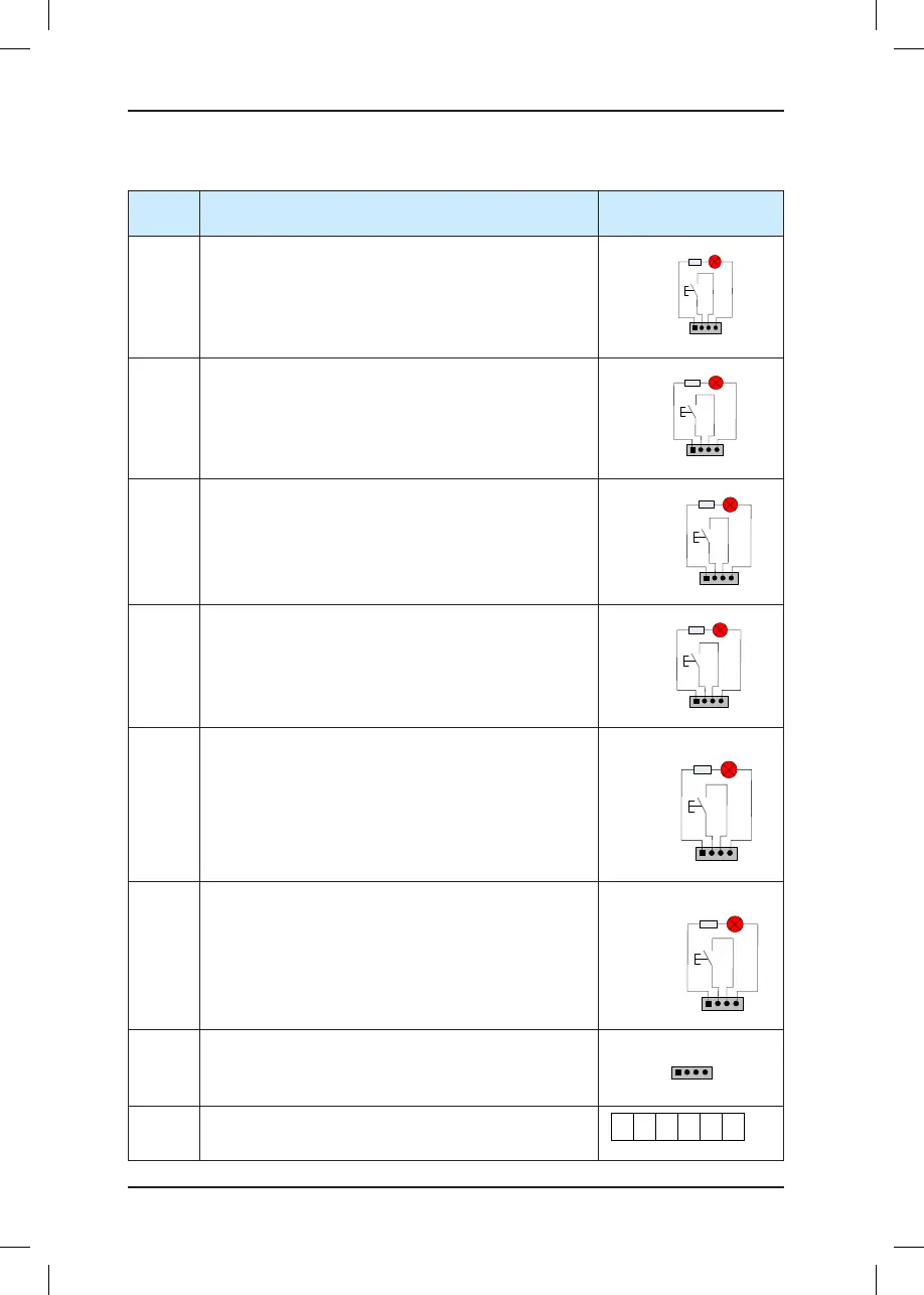
Table 3-12 Input and output terminals of HCB-B
Terminal
Name
Function Terminal Wiring
JP1
Interface for the elevator lock switch
Pins 2 and 3 are for switch input. Pins 1 and 4 are for
output of the elevator lock indicator.
1 2 3 4
Elevator lock indicator
Elevator
lock button
JP2
Interface for the re emergency switch
Pins 2 and 3 are for switch input. Pins 1 and 4 are for
output of the re emergency indicator.
1 2 3 4
Fire emergency indicator
Fire emergency
button
JP3
Interface for the up call button and indicator
Pins 2 and 3 are for up call input. Pins 1 and 4 are power
supply for the up call indicator.
1 2 3 4
Up call indicator
Up call button
JP4
Interface for the down call button and indicator
Pins 2 and 3 are for down call input. Pins 1 and 4 are
power supply for the down call indicator.
1 2 3 4
Down call indicator
Down call
button
JP5
Interface for the disability up call button and indicator
Pins 2 and 3 are for up call input. Pins 1 and 4 are power
supply for the up call indicator.
1 2 3 4
Disability up call
indicator
Disability up
call button
JP6
Interface for the disability down call button and indicator
Pins 2 and 3 are for down call input. Pins 1 and 4 are
power supply for the down call indicator.
1 2 3 4
Disability
down call
indicator
Disability
down
call button
CN1
Modbus communication and power supply terminal
Pins 2 and 3 are for Modbus communication. Pins 1 and
4 are for DC power supply.
CN2
Relay output
For the denition of the pins, see Table 3-13.