NICE5000 User Manual 5 System Commissioning and Functions
- 95 -
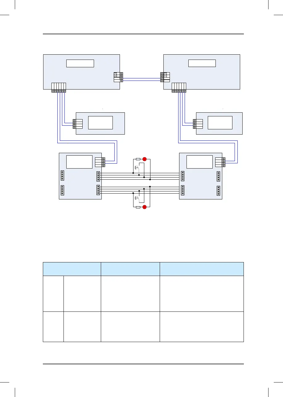
Figure 5-11 Wiring when CAN2 (CN6) is used for parallel control
NICE5000
CN3
CN6
CAN1+
CAN1-
CN2
24V
CAN+
CAN-
COM
MCTC-CTB
MCTC-HCB
24V
COM
Mod+
Mod-
1
2
3
4
Up button indicator
Up button
CN3
CN6
M24V
MCM
CAN1
+
CAN
1-
Mod1+
CN2
24V
CAN+
CAN-
COM
MCTC-CTB
MCTC-HCB
24V
COM
Mod+
Mod-
1
2
3
4
Elevator 1#
Elevator
1#
Elevator 2#
Elevator
2#
1
2
3
4
Down button indicator
Down button
1
2
3
4
1
2
3
4
JP3
JP4
JP1
JP2
1
2
3
4
JP3
JP4
1
2
3
4
JP1
JP2
1
2
3
4
CAN2
CAN
2
CAN2 cables for
parallel control
Mod
1-
M24V
MCM
Mod1+
Mod1-
NICE5000
+
-
CAN2
CAN2
+
-
5.5.3 Opposite Door Control
The NICE5000 implements opposite door control through Modbus interface. It supports
opposite door control on a maximum of 28 oors.
The following table describes the control modes and related parameter setting.
Table 5-7 Opposite door control modes and parameter setting
Opposite Door Control
Mode
Parameter Setting Function Description
Mode 1
Simultaneous
control
Fb-00 = 2
F8-24 = N (N > front door
maximum address)
Fb-01 = 0
The front door and back door acts
simultaneously upon arrival for hall
calls and car calls.
Mode 2
Hall call
independent,
car call
simultaneous
Fb-00 = 2
F8-24 = N (N > front door
maximum address)
Fb-01 = 5 (Bit0, Bit2 = 1)
The corresponding door opens upon
arrival for hall calls from this door.
The front door and back door act
simultaneously upon arrival for car
calls.