Specification TWINsync module
33
6 TWINsync operation modes
ID no.: CB08759-001Date: 03/2023
moog
The following figure shows the process data interface between the master and slave
drives and the process controller in the operation mode: "Rack and Pinion Drive
Control RPDC"
2605
4202
4202
4202
4203
26742666
2676
42034204
4203
MASTER
Motor 1
Motor 2
SLAVE
PRC
Figure
6.8:
Process
data
interface
and
process
controller
"Rack
and
pinion
drive
control
RPDC"
The transfer of the sent and received parameters is shown in the previous figure.
The communication between the master and slave is accomplished via the
TWINsync module. Here, the required current values and the speed setpoint are
transferred to the speed controller. The process controller (PRC) must be
parametrized for the slave unit. The transferred speed controller output from the
master unit serves as the specified setpoint. The slave unit delivers the current
speed controller output. The output of the process controller is a speed which is
added to the setpoint.
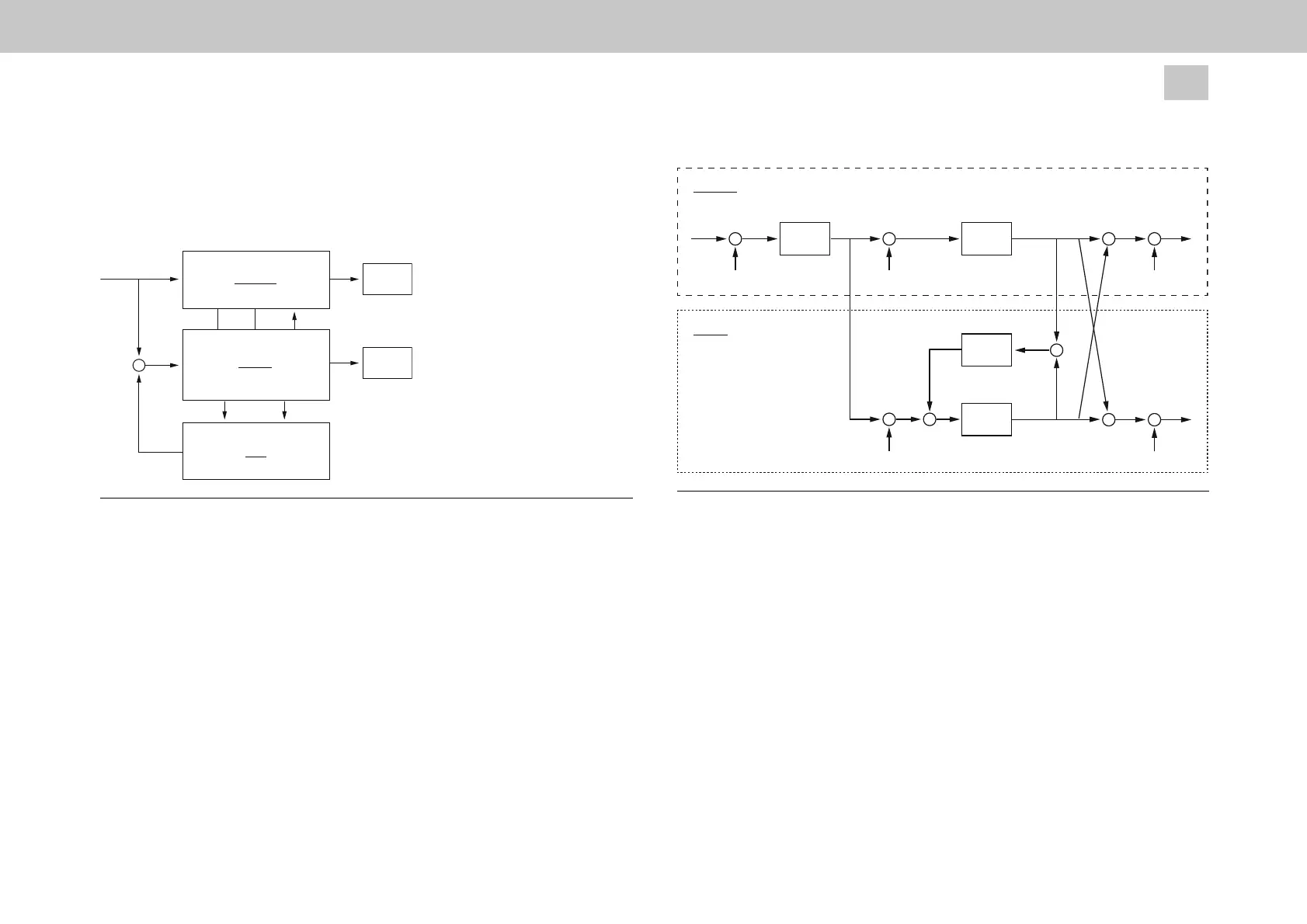
The following figure shows the control structure of the master and slave drives.
PCON
ε
ref
ε
act
n
ref
n
act,M
_ _
_
MASTER
i
sq, bias, M
SCON
n
act,S
_
i
sqref, scon, M
i
sqref, scon, S
i
sq, bias, S
SCON
PRC
SLAVE
Figure
6.9:
"Rack
and
pinion
drive
control
RPDC”
control
structure
The structure diagram of the RPDC is shown in the previous figure. It can be seen
here that the master operates with position control and the slave with speed control.
The process controller operates on the slave drive and ensures that both speed
controller outputs specify an identical current setpoint. Adding the two current
setpoints (master/slave) ensures that the same current is specified for both
machines. In order to now create a tension between the two drives, a current offset
must now be added to the machines. This offset ensures that the slave unit only
assists the master when the current setpoint exceeds the offset.