38
ع Setting the mark position offset
Use this screen to make the mark position offset.
Correct so that the cut start position is 12 mm away from the mark position.
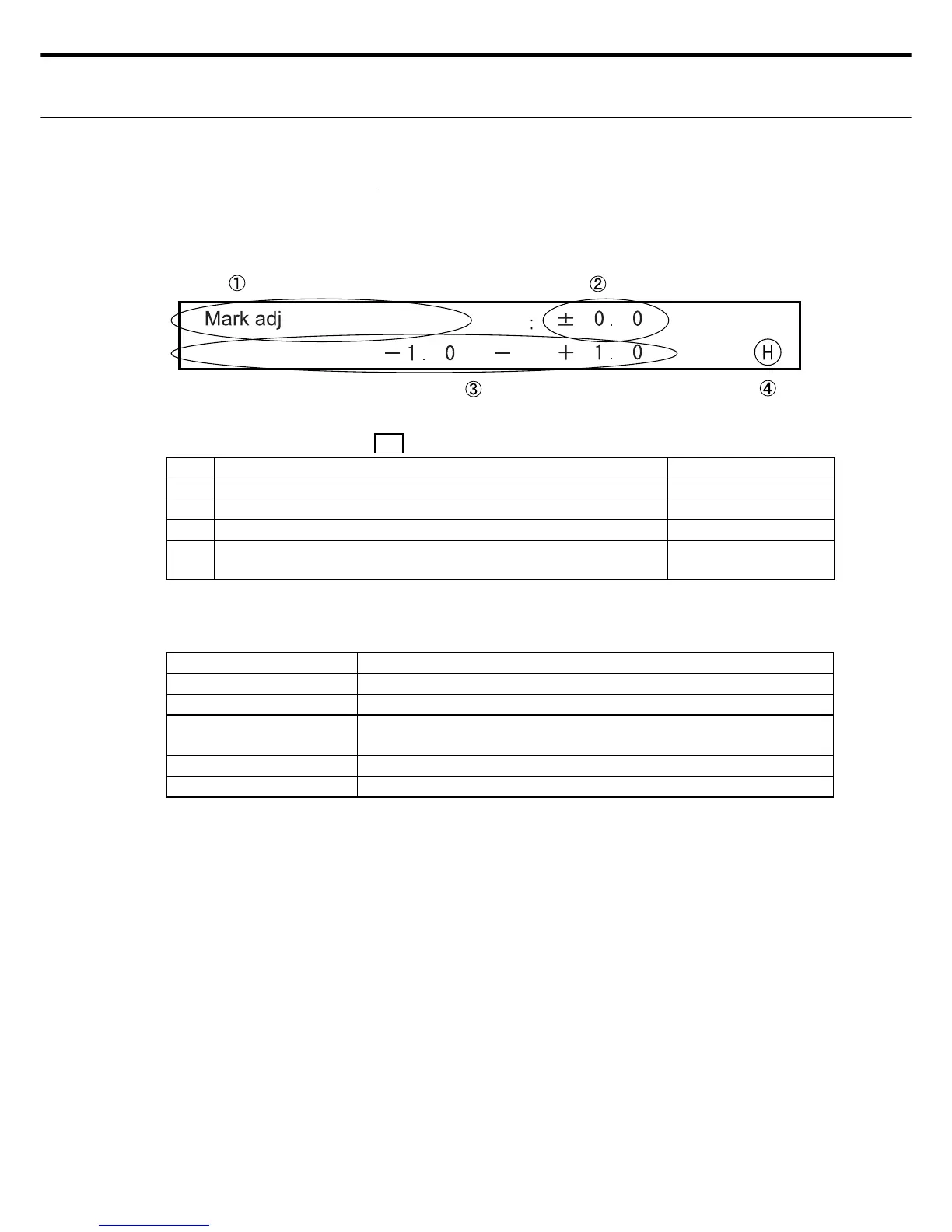
٤ LCD display for mark position offset
LED display Power LED: ON , READY : OFF, ERROR: OFF
No. Display information Display Changes
Ԙ Shows the screen for making the mark position offset setting INOP (fi xed screen)
ԙ Shows the mark position offset value. OK
Ԛ Shows the effective range of the mark position offset. INOP (fi xed screen)
ԛ An "H" appears when the display setting was saved. A blank
space appears during setting changes.
OK (Shows "H" or
blank display.)
Note : The only location settable by the user is ԙ .
٤ Switches for setting the mark position offset
Switches Description
RIGHT/LEFT Use for moving the cursor. Enabled by ԙ .
UP - DOWN Use for moving up or down to the number. Enabled by ԙ .
ENTER Use to store the settings. (After entering these, an "H" appears in
ԛ .)
CLEAR Shows the default values.
MENU Use in Setting Entry mode. Shifts to Menu screen Ԙ .
Note 1: The data changes are not stored if the Menu switch is pressed before the Enter
switch is pressed.
Note 2: If an error such as Cover-Open was detected before pressing the Enter switch, then
after eliminating the error, operation shifts to Standby mode without storing any of the
changes.