MiiNePort E2/E3 Introduction
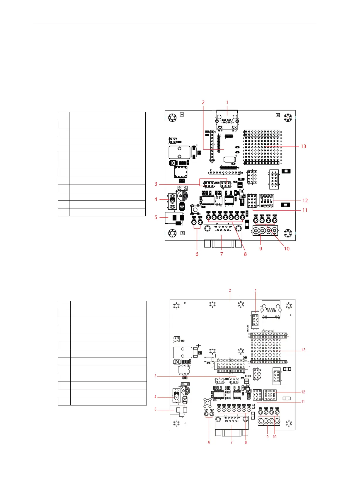
Panel Layout and Pin Assignments
Evaluation Board Layout
MiiNePort E2
1 Ethernet RJ45 Connector
2 MiiNePort E2 Module Location
3 Serial Interface Jumper
5 Power Jack
6 Power & Ready LED
8 Serial Port Status LED
9 Digital IO Terminal Block
10 Digital Output LED
11 Digital Input/Output Mode
12 Digital Input Switch
13 Circuit Pad
MiiNePort E3
1 PoE Pin
2 MiiNePort E3 Module Location
3 Serial Interface Jumper
4 Power Switch
5 Power Jack
6 Power & Ready LED
7 DB9 Male Connector
8 Serial Port Status LED
9 Digital IO Terminal Block
11 Digital Input/Output Mode
12 Digital Input Switch
13 Circuit Pad