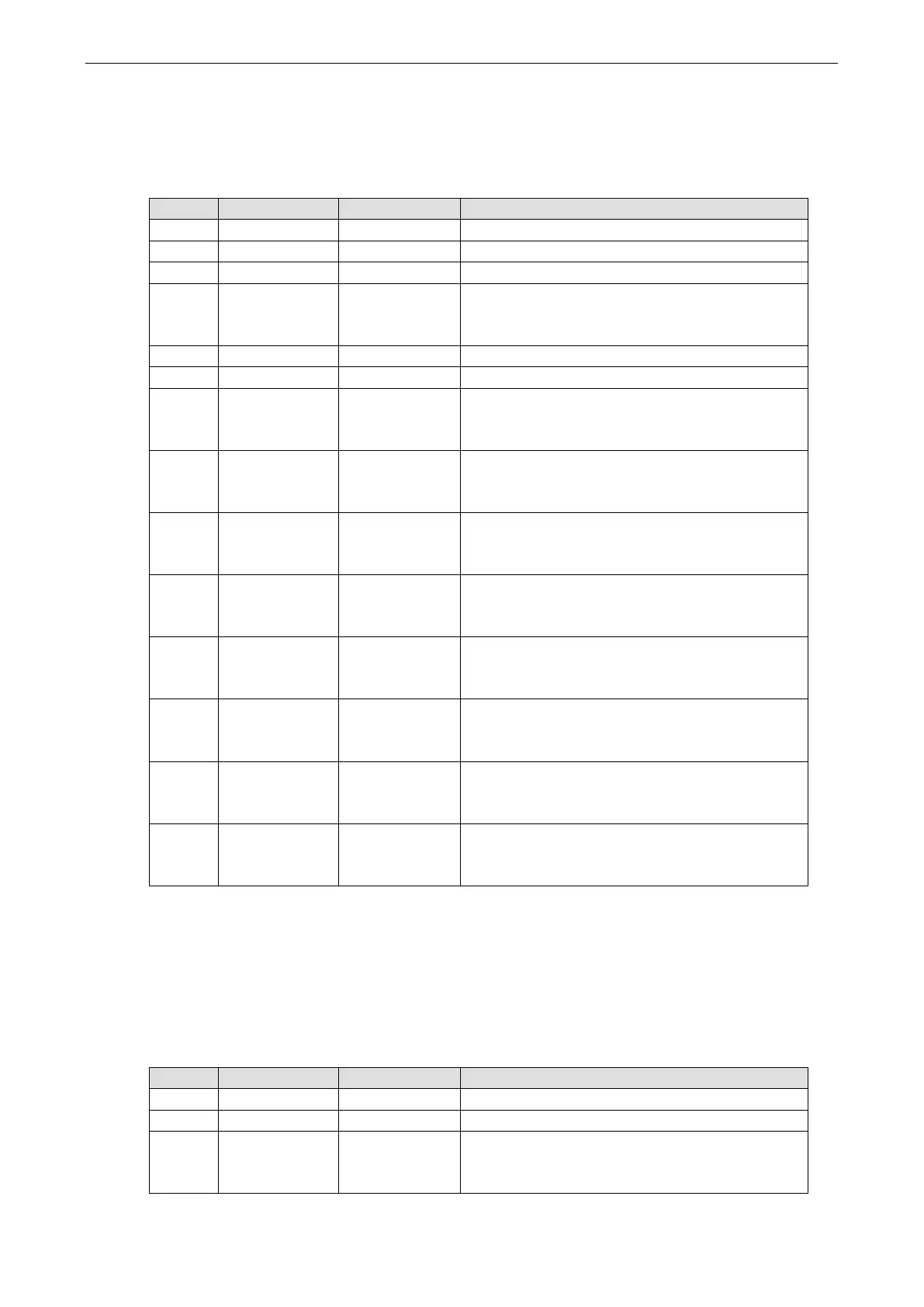
MiiNePort E2/E3 DIO Commands
Write Multiple DIOs
Command
Byte # Descriptor Value Description
1 Header 6 command number, fixed
2 Header 2 version, fixed
3 Header (any) this byte is only used in the module’s response
4 Header 6, 8, 10
data length, depends on the number of channels being
written (6 bytes for 2 channels, 8 bytes for 3 channels,
10 bytes for 4 channels)
5 Data 0, 1, 2 starting DIO channel number
6 Data 1, 2, 3 ending DIO channel number
7 Data 0,1 1st DIO channel to be written
0: set to input mode
1: set to output mode
8 Data 0, 1 1st DIO channel to be written
0: set to low
1: set to high
9 Data 0, 1 2nd DIO channel to be written
0: set to input mode
1: set to output mode
10 Data 0, 1 2nd DIO channel to be written
0: set to low
1: set to high
11 Data 0, 1 3rd DIO channel to be written, optional
0: set to input mode
1: set to output mode
12 Data 0, 1 3rd DIO channel to be written, optional
0: set to low
1: set to high
13 Data 0, 1 4th DIO channel to be written, optional
0: set to input mode
1: set to output mode
14 Data 0, 1 4th DIO channel to be written, optional
0: set to low
1: set to high
This command writes the status of a range of DIO channels, specified in bytes 5 and 6. The length of the
command depends on the number of channels to be written. For example, the 10-byte command
6-2-0-6-0-1-0-0-1-1 requests DIO 0 be set to digital input mode and “low” status and DIO 1 be set to digital
output mode and “high” status. If you wanted to include a change of DIO 2 to digital output mode and “low”
status, the 12-byte command sequence would be 6-2-0-8-0-2-0-0-1-1-1-0.
Response
Byte # Descriptor Value Description
1 Header 6 command number, fixed
2 Header 2 version, fixed
3 Header 0, 1, 2, 3,
4, 5, 6,
0xFF
command status/error code (0 = okay)