MiiNePort E2/E3 Getting Started
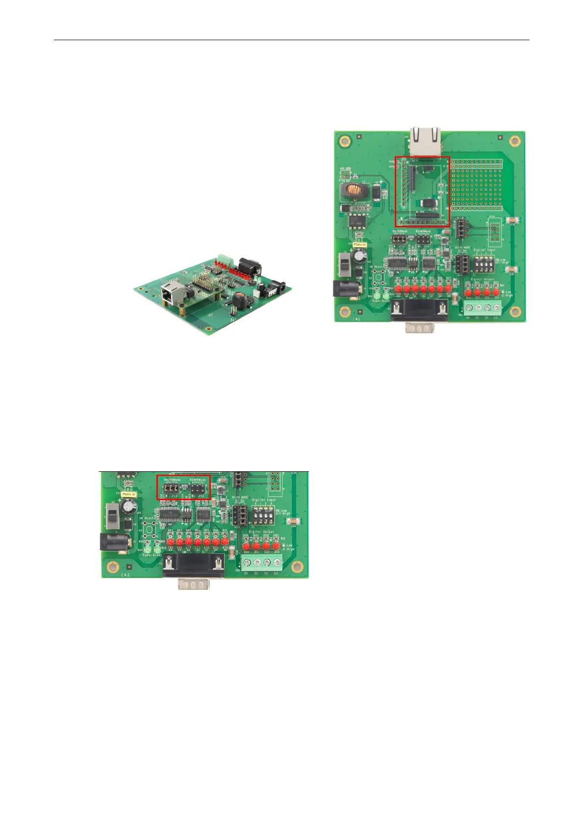
Installing the MiiNePort module onto the
MiiNePort Evaluation Board
Before using the MiiNePort evaluation board with the
module, be sure to disconnect the power supply, network,
and serial device. A profile of the MiiNePort is shown in the
center of the evaluation board
near the top. The profile
indicates where you should install the module onto the
evaluation board (refer to the figure at the right). When
attaching the module to the evaluation board, make sure
the module is securely installed on the evaluation board.
Af
ter the module is installed, connect the power supply,
network, and serial device to the evaluation board.
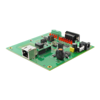
MiiNePort E2
Selecting the Serial Interface
The MiiNePort module uses a standard TTL serial signal input. However, to make the evaluation more
convenient, the evaluation board has built-in RS-232 and RS-485 interfaces. Use a 6-pin jumper to select which
serial interface is active.
• RS-232: short the 6-pin jumper to JP13
• RS-485: short the 6-pin jumper to JP14