Do you have a question about the MTE HYDROCAL 1001 Plus and is the answer not in the manual?
Describes recommended and prohibited installation locations on a transformer.
Outlines essential safety measures for installation and operation.
Covers necessary steps and tools required before physically installing the unit.
Details how to connect the unit's electrical cables to the power supply.
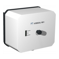
Identifies the components visible on the front of the HYDROCAL unit.
Identifies rear connections, including supply voltage and system interfaces.
Details internal connections, LEDs, buttons, and terminals on the main board.
Explains the external LEDs for system status, gas, and moisture levels.
Describes internal LEDs and buttons for monitoring and special functions.
Details special functions like firmware updates, functional tests, and test modes.
Lists measurement quantities, ranges, accuracies, and TDCG contributions.
Details the specifications for analog DC and digital relay outputs.
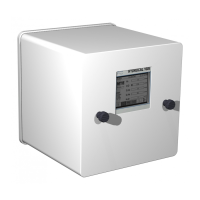
Provides the overall physical dimensions of the HYDROCAL unit with measurements.
Shows detailed dimensions for G 1½" ISO DIN 228-1 and 1½" NPT ANSI B 1.20.1 connection threads.
| Brand | MTE |
|---|---|
| Model | HYDROCAL 1001 Plus |
| Category | Measuring Instruments |
| Language | English |