HYDROCAL 1001+ Installation and operation manual Page 31/76
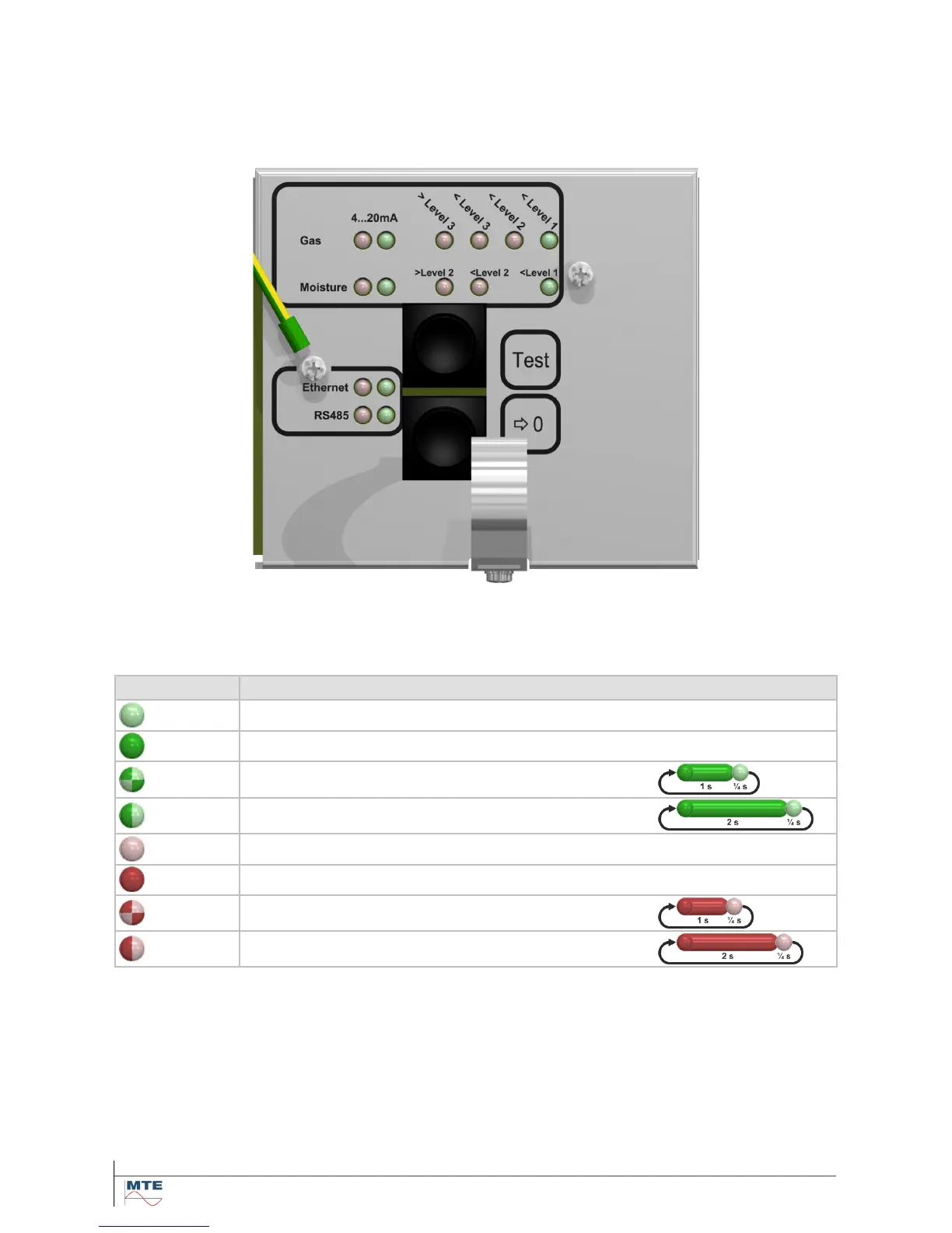
4.3. Internal user interface
The internal user interface consists of 15 single color light-emitting diodes (LEDs) to reflect the sys-
tem status and two push buttons to allow the activation of special functions. Under normal conditions
the LEDs reflect the status of the communication interfaces, analog outputs and gas concentration
(absolute, daily- and weekly trend) and moisture concentration:
During special operations the LEDs are used in another manner to reflect the status or progress of
the related task.
The icons of the single color LEDs (green or red) have the following signification:
Description Color sequence
Green LED permanently off -
Green color permanently on -
Green color short on (~1 s on / ~¼ s off)
Green color long on (~2 s on / ~¼ s off)
Red LED permanently off -
Red color permanently on -
Red color short on (~1 s on / ~¼ s off)
Red color long on (~2 s on / ~¼ s off)
Note: The signification of the LED status you can find in the following tables of the internal user inter-
face. The speed of the toggling or flashing LEDs varies and is defined with e.g. (~1 s on / ~1 s off).