HYDROCAL 1001+ Installation and operation manual Page 27/76
4. Firmware
4.1. General information
The composite Gas-in-Oil sensor with moisture in oil measurement HYDROCAL 1001+ is based on a
microprocessor controlled measurement system. A 32 Bit „Coldfire“ processor with a clock frequency
of 240 MHz is used. The system has a FLASH memory of 32 Mbyte for permanent storing of the
measurement data, which offers a storage capacity of 2 years. After this period, the oldest data will
be overwritten by the latest values.
Attention !!!
To avoid any loss of data, it is proposed to read out regularly the
measurement data by the Windows based software Hydrosoft.
The HYDROCAL 1001+ does not have a graphical display but is equipped with two user interfaces:
External user interface (4.2)
Internal user interface (4.3)
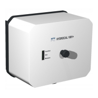
4.2. External user interface
The external user interface is located on the component side of the measurement- and controller
card and is facing toward the front of the HYDROCAL unit. It has 3 multicolor light-emitting diodes
(LED) to reflect the system status (function) and to indicate gas- and moisture concentration as well
as the daily and weekly gas trend.
Function LED (4.2.1)
Gas LED (4.2.2)
Moisture LED (4.2.3)
The icons of the multicolor LEDs have the following signification:
Status Description Color sequence
off LED permanently off -
on White color permanently on -
on Green color permanently on -
on Yellow color permanently on -
on/off fast Yellow color short on (~1 s on / ~¼ s off)
on/off slow Yellow color long on (~2 s on / ~¼ s off)
on Red color permanently on -
on/off fast Red color short on (~1 s on / ~¼ s off)
on/off slow Red color long on (~2 s on / ~¼ s off)
Note: The signification of the LED status you can find in the following tables of the external user in-
terface LED.