HYDROCAL 1001+ Installation and operation manual Page 28/76
4.2.1. Function LED
The HYDROCAL unit contains an internal system monitoring which is assigned to the function LED
and relay output 4 (connection terminal X2:7&8). The following internal error sources are monitored:
Loss of time
Data memory not ready
RTC not ready (buffer capacitor empty)
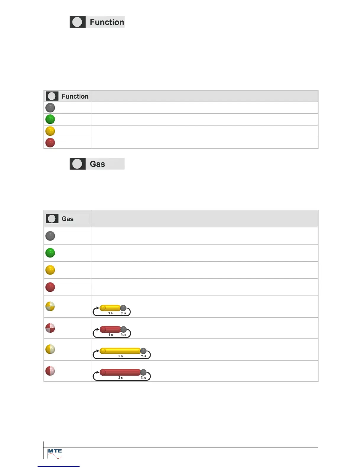
The multicolor function LED illustrates the status of the internal system monitoring as follow:
System monitoring not active
System monitoring active - system okay - relay switched on
System monitoring active - system has monitored an error - relay switched off
4.2.2. Gas LED
The HYDROCAL unit contains an alarm level monitoring (absolute gas concentration, gas concentra-
tion daily trend and gas concentration weekly trend), which is assigned to the gas LED, the relay out-
put 1 for level 1 (High) alarm (connection terminal X2:1&2) and the relay output 2 for level 2 (High-
High) alarm (connection terminal X2:3&4).
The multicolor LED illustrates the general status (only one alarm triggered) as follow:
Description /
Color sequence
Alarm level monitoring not active
-
Absolute gas concentration – level 1 (High) alarm is triggered /
-
Absolute gas concentration – level 2 (High-High) alarm is triggered /
-
Gas concentration daily trend – level 1 (High) alarm is triggered /
Gas concentration daily trend – level 2 (High-High) alarm is triggered /
Gas concentration weekly trend – level 1 (High) alarm is triggered /
Gas concentration weekly trend – level 2 (High-High) alarm is triggered /
As the alarms for gas concentration (absolute, daily- and weekly trend) can be present in parallel the
individual status of the gas LED is illustrated as following patterns:
Note: In order to simplify the illustration in the pattern table the level 1 (High) alarm is named as 1
and level 2 (High-High) alarm as 2. No alarm active is named as 0.