HYDROCAL 1001 Manual for Installation and Operation Page 1/72
Table of Content
1. General..................................................................................................................................... 3
2. Installation instructions .......................................................................................................... 4
2.1. Installation positions ............................................................................................................. 4
2.2. Safety precautions ................................................................................................................ 5
2.3. Installation preparation ......................................................................................................... 7
2.3.1. Mechanical connection .................................................................................................. 7
2.3.1.1. Flange connection .................................................................................................. 7
2.3.1.2. Fitting with union nut ............................................................................................... 7
2.3.2. Auxiliary supply connection ........................................................................................... 8
2.3.3. Required tools ............................................................................................................... 8
2.3.4. Sealing the connection thread ....................................................................................... 8
2.3.4.1. Thread seal tape..................................................................................................... 8
2.3.4.2. Thread sealant ....................................................................................................... 9
2.3.4.3. Flat sealing (gasket) ............................................................................................... 9
2.4. Installation .......................................................................................................................... 10
2.4.1. Mechanical installation ................................................................................................. 10
2.4.1.1. Direct installation .................................................................................................. 11
2.4.1.2. Indirect installation ................................................................................................ 12
2.4.2. Electrical connection .................................................................................................... 14
2.4.3. Putting into operation ................................................................................................... 15
3. Hardware components .......................................................................................................... 16
3.1. Front view ........................................................................................................................... 16
3.2. Rear view ........................................................................................................................... 17
3.3. Connections of measurement- and controller card .............................................................. 19
3.3.1. Beeper ......................................................................................................................... 22
3.4. Connections of power supply card ...................................................................................... 23
3.5. Wiring of the heating resistors ............................................................................................ 24
3.5.1. Wiring heating resistors for 230 V ................................................................................ 25
3.5.2. Wiring heating resistors for 120 V ................................................................................ 26
4. Firmware ................................................................................................................................ 27
4.1. General information ............................................................................................................ 27
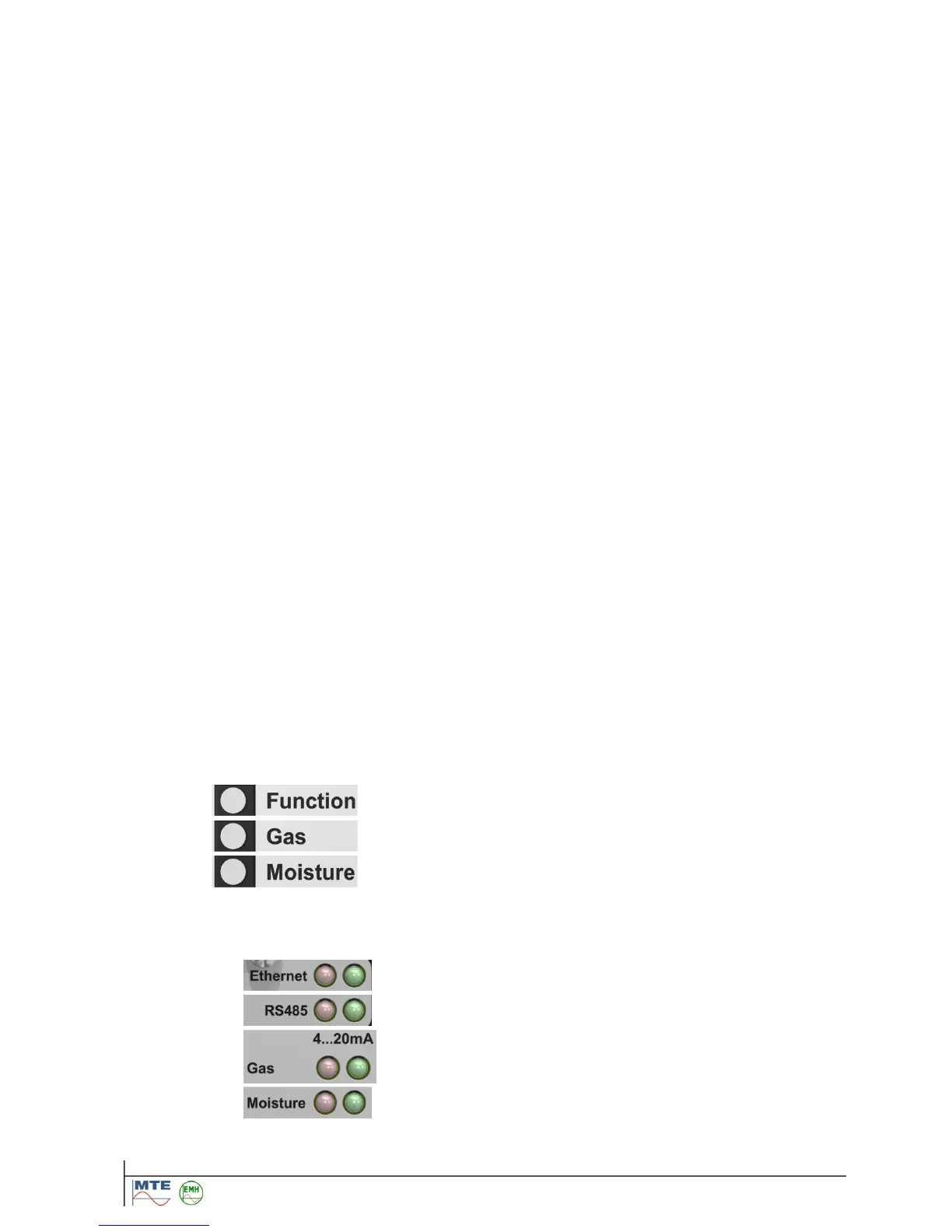
4.2. External user interface ........................................................................................................ 27
4.2.1. Function LED .............................................................................. 28
4.2.2. Gas LED ..................................................................................... 28
4.2.3. Moisture LED .............................................................................. 30
4.3. Internal user interface ......................................................................................................... 31
4.3.1. Normal Operation ........................................................................................................ 32
4.3.1.1. LED & energy save mode ..................................................................................... 32
4.3.1.2. LED Ethernet ........................................................................... 32
4.3.1.3. LED RS485 ............................................................................. 32
4.3.1.4. LED Gas analog output .......................................................... 33
4.3.1.5. LED Moisture analog output .................................................... 33