Art.-No. 57106 PROFINET IO bus node
User manual 57106_hdb_en_13 51 / 94
10.2 Structure
57106
10.3 Interfaces
CAUTION!
Power module and bus interface as well as power and terminal module
each form one unit!
Separating destroys the modules.
Do not separate power module and bus interface or power and terminal
module!Disconnecting destroys the modules.
Connecting terminal Connect the wires with a cross section of 0.08 mm
2
(AWG 28) up to 1.5 mm
2
(AWG 16).
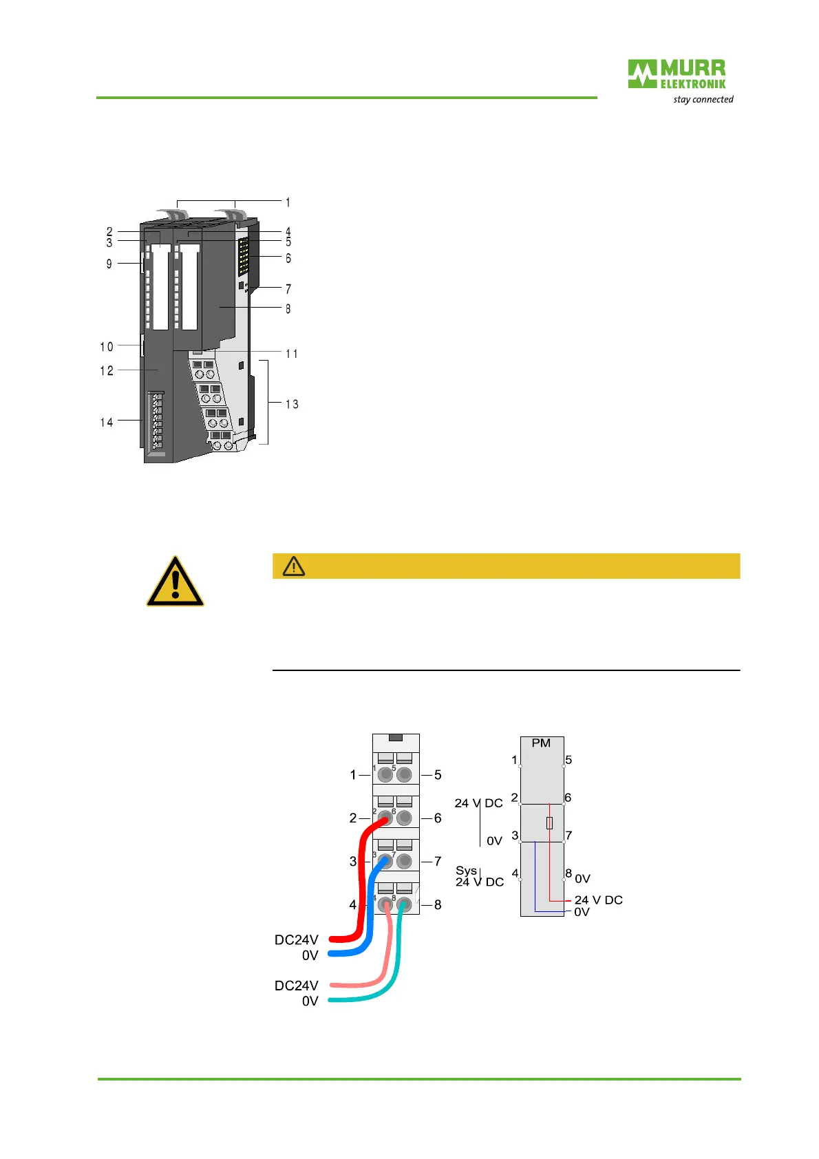
Fig. 10-2: Design of PROFINET IO bus node
1 Locking lever of terminal module
2 Labeling strip of bus interface
3 LED status indication of bus interface
4 Labeling strips of power module
5 LED status indication of power module
6 Backplane bus
7 24 V DC power supply
8 Power module
9 PROFINET RJ45 bus interface P1
10 PROFINET RJ45 bus interface P2
11 Power module unlocking
12 Bus interface
13 Connecting terminal
14 Address switch

 Loading...


