April 27, 2015 1-5
Introduction
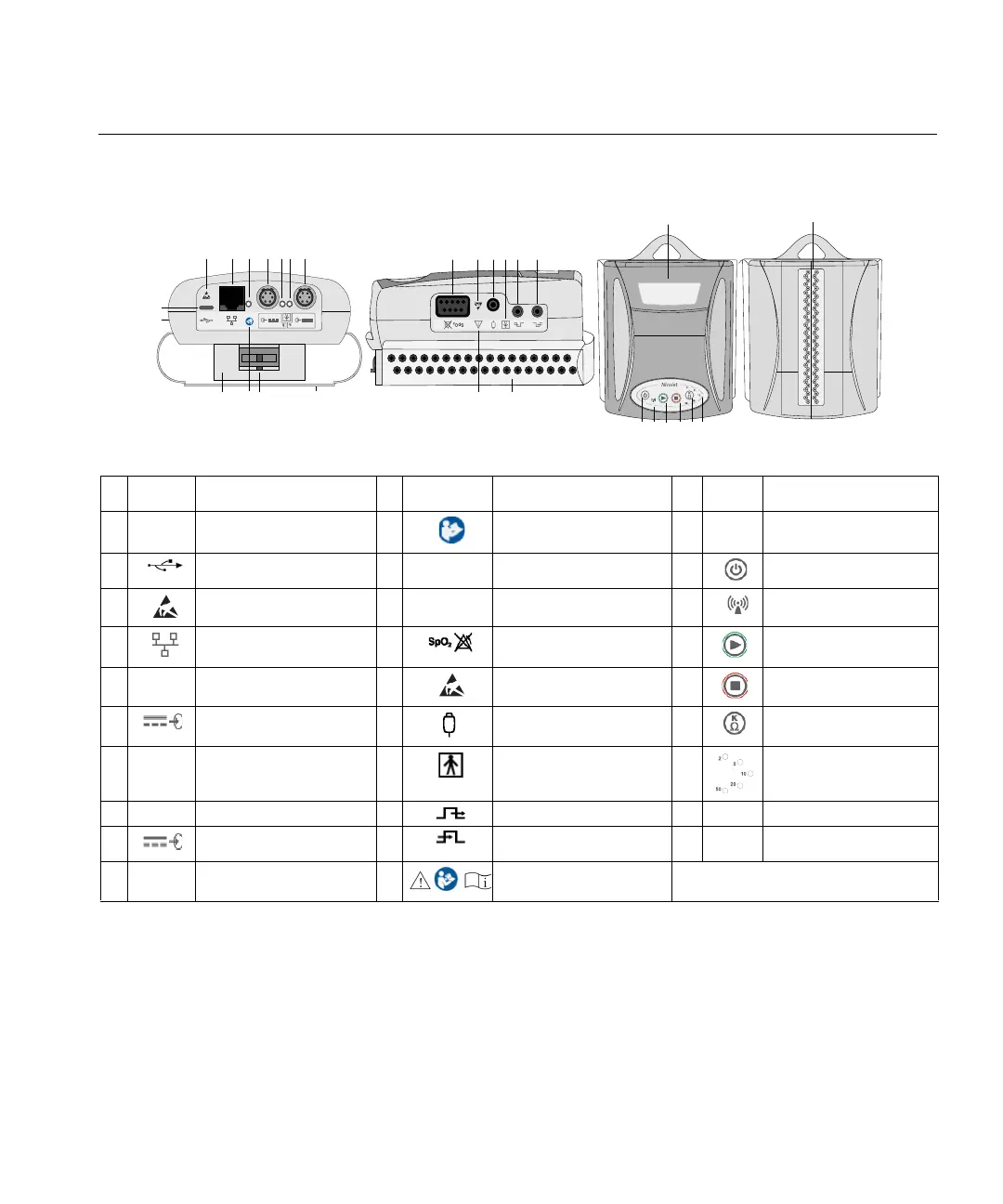
Nicolet EEGwireless32/64 amplifier symbols and components
AA
Z
T
U
V
W X Y
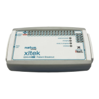
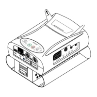
Nicolet wirelessEEG32A
M
N O P
S
R
Q
B
E
F
D
K
H
С
A
G
I
J
L
AB
AC
NOTE: External power from Inputs F and I are interchangeable between two external batteries and a medical power supply.
Symbol Description Symbol Description Symbol Description
A-
Amplifier
K
Refer to page j in this manual.
U-
Electrode inputs (each side)
B
Diagnostic port
L-
Disconnect headbox latch
V
Power on/off button
C
Electrostatic sensitive
M-
Electrode leads cover
W
LED - Wireless transmission on
D
Network port
N
SpO2
X
Start recording button
E-
LED - Ethernet connectivity
O
Electrostatic sensitive
Y
Stop recording button
F
Power input for external batteries
or power supply
P
Event button input
Z
Impedance check button
G-
LED - Power connectivity
Q
Type BF equipment
AA
LEDs - Impedance range
H-
LED - Power connectivity
R
Trigger output (for Photic, etc.)
AB -
Battery door, under headbox
I
Power input for external batteries
or power supply
S
Trigger input
AC -
LEDs - Impedance check
J-
32 or 64 headbox
T
Refer to page j in this manual.
 Loading...