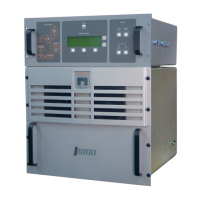
10 000 WATT FM BROADCAST TRANSMITTER
FM10
Page 6-9
15 November 1999
indications for remote metering, B+ VOLTS SAMPLE
(TB1-16) and TOTAL CUR SAMPLE (TB1-17) which
provide final amplifier DC voltage and current level
indications for remote metering. Digital status
outputs, when active, provide current sinks to ground
which will sink current from an external positive
supply. When inactive, these status outputs are high
impedance. The IPA/RF FAIL
(TB2-1), PA/SUPPLY
FAIL (TB2-2), HIGH REFLECTED POWER (TB2-3),
AC FAULT
(TB2-4), HIGH TEMP
(TB2-5), PA
VDC/COMBINER
(TB2-6), INTERLOCK
(TB2-7), FAN
FAIL (TB2-8), RF ON STATUS
(TB2-9), XMTR
READY
(TB2-10), REMOTE STATUS (TB2-11) and
LOW BATTERY ALARM
(TB2-17) outputs are all
driven by the control/monitor PWB.
6.5.2.3 Local/Remote Control Selection: See
figures SD-9 and SD-10. The local/remote control
status is selected by momentarily pressing either the
LOCAL CONTROL switch (A13A1S4) for local
control of the transmitter or the REMOTE CONTROL
switch (A13A1S5) for remote control of the
transmitter. When remote control is selected, the
local inputs have no influence with the exception of
the RF OFF switch (A13A1S7), which is always
active. This feature permits the RF power stages to
be turned off locally in the event of an emergency.
6.5.2.4 RF On/Off Control: See figures SD-9
and SD-10. The transmitter's RF power stage is
controlled locally by RF ON
and RF OFF switches and
remotely by the REMOTE RF ON
(+) (-) and REMOTE
RF OFF (+) (-) control inputs. The RF ON switch is
disabled when the REMOTE CONTROL switch has
been pressed and the remote RF on and remote RF
off controls are disabled when the LOCAL CONTROL
switch has been pressed. The RF OFF switch is
enabled in RF ON
both local and remote control.
When the condition is enabled (locally or remotely),
the exciter interlock changes state to enable the
exciter, the RF ON
indicator LED is turned on, the
remote RF on status is enabled (current sink), J6-6
will switch to 5 VDC (RF On) causing the low
voltage power supply to supply 24 VDC to the
cooling fans and the inhibit will be removed from the
IPA Volts Control output (J8-12/11) allowing the
IPA switching power supply to provide an IPA volts
supply to the IPA module. When the RF OFF
condition is enabled (locally or remotely), the exciter
interlock will mute the exciter's output, the RF ON
indicator LED will turn off, the remote RF on status
is disabled (open circuit), J6-6 will switch to ground
(RF On) causing the low voltage power supply to
remove the 24 VDC supply from the cooling fans and
an inhibit (ground) will be placed on the IPA Volts
Control output (J8-12/11) to turn off the IPA
switching power supply and inhibit the transmitter
RF output. The Alarm Reset signal (J9-10) is
activated (5 VDC) during the RF on condition to
prevent false alarm indications.
6.5.2.5 Transmitter Interlock: See figures SD-9
and SD-10. The transmitter safety interlock circuit
will influence the RF status to prevent transmitter
operation when the interlock is open. If the interlock
circuit is opened, the
INTERLOCK OPEN indicator
LED will turn on and the RF ON
indicator LED will
turn off or remain off. The circuitry will function as
if the RF OFF switch had been pressed (see para
.6.5.2.4). 5 VDC will be applied to the Alarm Inhibit
line during the interlock open condition to prevent
other transient alarms. When the interlock circuit is
closed, INTERLOCK OPEN indicator LED will turn
off when ALARM RESET is momentarily pressed. If
the RF was on previous to the interlock being opened,
the RF ON indicator LED will turn on and the RF
output will be exponentially restored to its previous
level.
6.5.2.6 Transmitter Output Power Level
Adjustment: See figures SD-9 and SD-10. The
magnitude of the low level DC PA Volts Control
output (J6-1/3) determines the output voltage level
applied to the RF power modules (A thru F) from the
switching power supplies (A thru F) and hence the
output power level of the transmitter. This voltage is
generated by a counter circuit and a digital to analog
converter which allows adjustment of the control
voltage from a minimum of 0.0 VDC to a maximum
of approximately 7.5 VDC in 256 discrete steps.
Each time the POWER RAISE switch (A13A1S8) is
momentarily pressed, a ground is applied to the Pwr
Increase input (J2-39) and is detected by the counter
circuit. The counter circuit's total count will increase
by one (until a maximum count of 256 is reached
corresponding to maximum output power) and the
transmitter's output power will increase by the
corresponding increment. If the POWER RAISE
switch is pressed and held, after a brief pause the
transmitter's output power will begin to continually
increase until the POWER RAISE switch is released or
until maximum output power has been reached. Each


 To Next Page