10 000 WATT FM BROADCAST TRANSMITTER
FM10
Page 5-10
01 October 2002
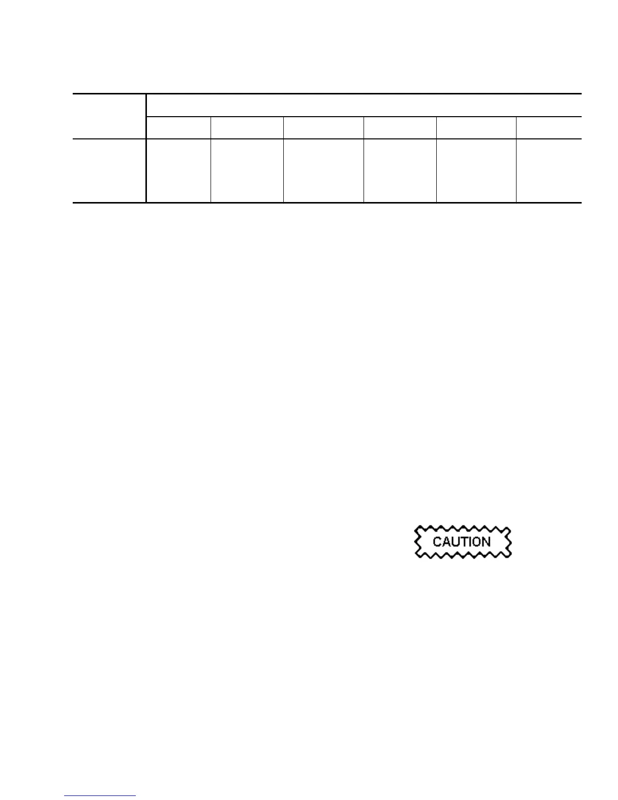
Table 5-4 Component Association for Tuning
COMPONENT POWER AMPLIFIER CHANNEL
1 2 3 4 5 6
INPUT PA A2 A4 A6 A8 A10 A12
OUTPUT PA A1 A3 A5 A7 A9 A11
TUNE SWITCH A13S2-1 A13S1-2 A13S1-1 A13S2-2 A13S3-1 A13S3-2
RF OUTPUT J1 J2 J3 J4 J5 J6
P2 of cable assembly 161-5017 mates with the
connector that was originally connected to J8 of
the removed RF power module.
- One end of the black, 8AWG ground wire in
cable assembly 161-5017 connects to the RF
power module's ground stud, using the studs'
original attaching hardware. The other end
connects to the rear of RF power module tray.
(e) Select either 'E' or 'F' RF power module as the
tuning PA volts source (for module to be tuned)
and then turn the module off by setting its PWR
MDL circuit breaker to off.
- Insert the PA volts extender cable between J7
of the RF power module ('E' or 'F') which was
turned off and the PA volts cableform
connector which mates with it.
NOTE
Do not connect P2 of the extender cable to J7 of the
RF power module to be tuned at this time.
- If the transmitter is on-air, restore the RF
contribution of the RF power module being
used as the PA volts source, by setting its PWR
MDL circuit breaker to on.
5.7.2.3 Tuning Procedure: Tune a repaired
input/output power amplifier after it has been re-
installed in its RF power module as follows:
NOTE
Reference is made to input/output power amplifier
pairs and an associated NORMAL/TUNE switch in
the following procedures. Refer to table 5-4 to
identify which components are associated with a
power amplifier channel, noting there are six
channels. If necessary, refer to the assembly detail
illustrations in the RF power module's service
instruction manual to identify/locate a specific
component.
The metal covers for the input/output power
amplifiers must be installed and their attaching
hardware firmly tightened during tuning
procedures.
(a) Using a digital multimeter, measure the DC
voltage between TP1 of the PA switching
power supply associated with the RF power
module selected as the PA volts source and
chassis ground. It should be 45.0 VDC when
ƒ
c is between 87.9MHz and 98.0MHz or 46.5
VDC when
ƒ
c is between 98.1MHz and
107.9MHz.
NOTE
The PA volts being applied to an RF power module
being tuned must be 45.0 VDC when
ƒ
c is between
87.9MHz and 98.0MHz or 46.5 VDC when
ƒ
c is
between 98.1MHz and 107.9MHz. Since the RF
output is a product of this voltage, it may be
necessary to increase or decrease the RF output
during tuning procedures.
An RF output in excess of 7000 watts may be
applied to the antenna system when five RF power
modules are operational and the PA volts is set to
45.0/46.5 VDC If 7000 watts exceeds the
maximum RF that can be applied to the antenna, It
will be necessary to connect the output of the
transmitter to a suitably rated dummy load during
tuning procedures.
(b) If requirements of step (a) are not met,
increase/decrease the RF output using the
TRANSMITTER OUTPUT POWER - RAISE and
LOWER switches until the pa volts is the
required level.
 Loading...


