10 000 WATT FM BROADCAST TRANSMITTER
FM10
Page 5-7
01 October 2002
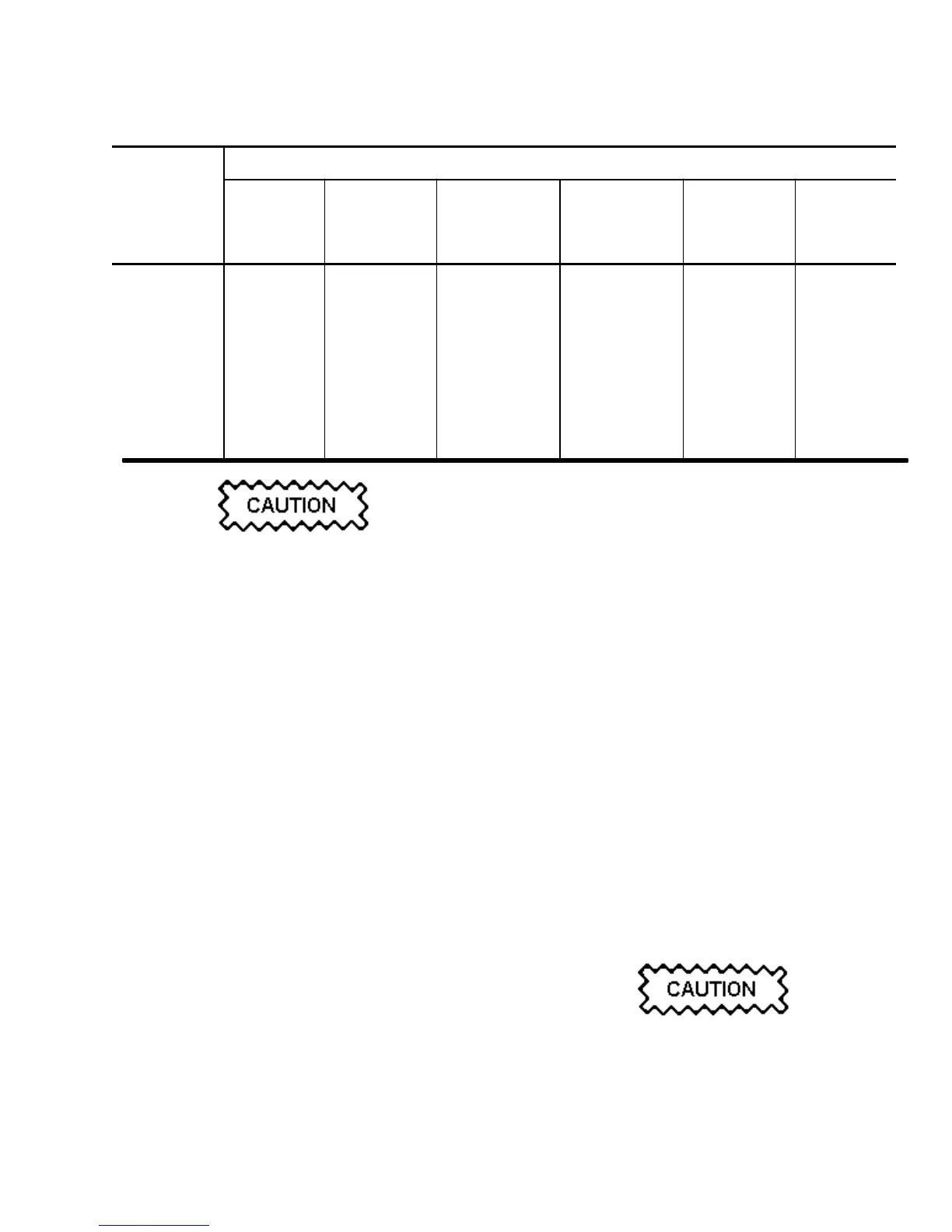
Table 5-3 Power Module Mating Connectors
MATING CONNECTORS FOR
PWR
MODULE PWR PWR PWR PWR PWR PWR
CONNECTOR MODULE MODULE MODULE MODULE MODULE MODULE
A B C D E F
J1 W1P1 W7P1 W13P1 W19P1 W25P1 W31P1
J2 W2P1 W8P1 W14P1 W20P1 W26P1 W32P1
J3 W3P1 W9P1 W15P1 W21P1 W27P1 W33P1
J4 W4P1 W10P1 W16P1 W22P1 W28P1 W34P1
J5 W5P1 W11P1 W17P1 W23P1 W29P1 W35P1
J6 W6P1 W12P1 W18P1 W24P1 W30P1 W36P1
J7 P35 P36 P37 P38 P39 P40
J8 P5 P6 P7 P8 P9 P10
J9 W41P2 W42P2 W43P2 W44P2 W45P2 W46P2
The RF coaxial cable interconnecting the output of
the intermediate RF drive splitter and the RF
power module's RF drive input must be
disconnected from the RF drive splitter end before
it is disconnected from the RF power module.
Failure to observe this disconnection sequence will
cause an impedance mismatch to be reflected back
to the intermediate RF drive splitter and may result
in a high IPA reflected power that will cause the
transmitter to shut down.
(i) At the intermediate RF drive splitter end, locate
the RF drive coaxial cable identified in step (h)
and disconnect it.
(j) Disconnect the RF drive coaxial cable identified
in step (h) from J9 of the RF power module to
be removed.
(k) Disconnect the PA volts connector (3-pin) from
J7 of RF power module to be removed.
(l) Disconnect the 9-pin connector from J8 of RF
power module to be removed.
(m) Free the RF power module to be removed, from
its mounting tray, by removing the attaching
hardware (nuts and washers) from both ground/
retaining studs, noting the studs protrude thru
the mounting tray at the rear of the module.
(n) Carefully withdraw RF power module from the
front of the cabinet.
NOTE
If a serviceable RF power module is available,
install it as detailed in paragraph 5.7.3. If a
serviceable RF power module is not available, the
transmitter may remain on-air provided not more
than two RF power modules have been removed.
(o) Repair a defective RF power module as detailed
in its service instruction manual, noting final
tuning of repaired input/output power
amplifiers must be completed in accordance
with the instructions in paragraph 5.7.2 before
the RF power module is re-installed in a
transmitter.
5.7.2 RF POWER AMPLIFIER TUNING:
Tune the input impedance of any 'input power
amplifier' and the output impedance of any 'output
power amplifier' that has been repaired, to precisely
50 ohms as follows:
Do not install RF power modules that have
untuned power amplifiers (input or output) in a
transmitter. Failure to observe this precaution
may result in a transmitter shut down or an
impedance mismatch that may destroy solid state
devices.
 Loading...


