2-6 BenchMike Pro 2025/2050 & Z-Mike Pro 4025/4050 Instruction Handbook: Installation
2.3 Connections
2.3.1 Connecting the BenchMike Pro to Your PC
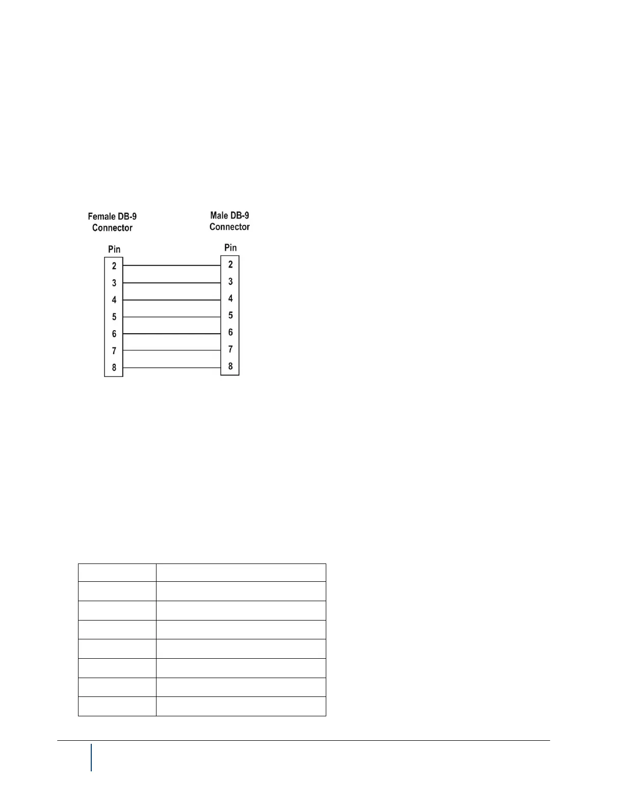
Use the BenchMike Pro’s serial port, labeled Serial #1, to connect your PC to the BenchMike Pro. The cable used
to connect the BenchMike Pro and PC should be a shielded, straight-through cable with a DB-9 female connector
on one end and a DB-9 male connector on the other end. A straight-through cable can be purchased from most
electronic and computer stores. The drawing below shows the wiring for a straight-through cable.
2.3.2 Digital I/O Connector
The digital I/O connector is a DB-25 connector. The number of inputs and outputs on a BenchMike Pro will vary
based on the number ordered by the customer.
There is a maximum of 8 software-readable inputs, supports level or transition detection, and each input is pulled
up to 5 V with a 4.7K resistor.
Alarm outputs are open-collector, with a maximum voltage of 35 V DC. The output current is 250 mA per output.
Individual outputs have selectable NO or Not Connected states.
The following table shows the pin definitions of this connector.