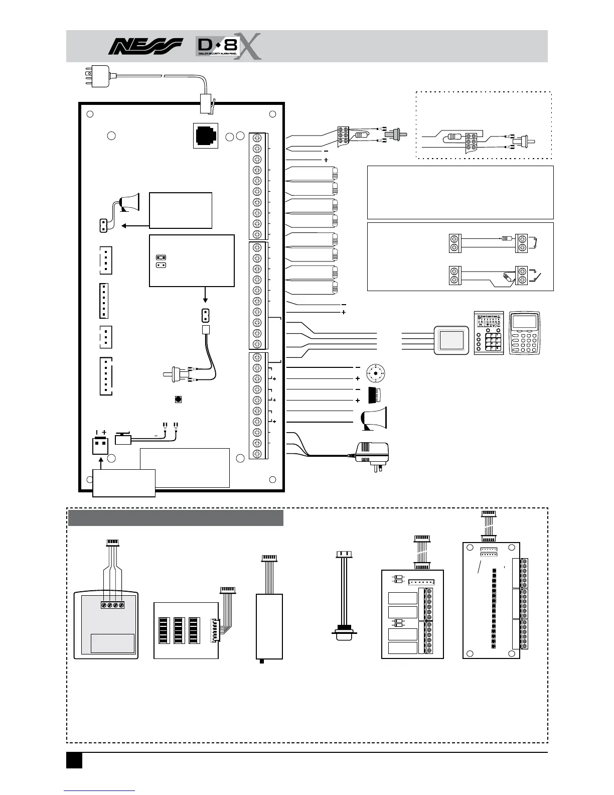
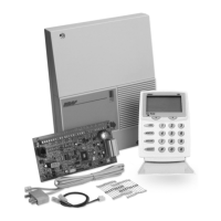
D8x CONNECTION DIAGRAM
8
Ness D8x / D16x Control Panel – Installation Manual
J1
RECEIVERLISTEN SERIAL
READER
PROG
TAMP
BATTERY
RED +
TELEPHONE
HEATSINK
AUX1
AUX2
AUX3
AUX4
+12V
0V
TAMP
+12V
+12V
+12V
0V
Z8
C
Z7
Z6
C
Z5
Z4
C
Z2
Z3
C
Z1
0V
CLK
DAT
COM
KEYPAD
RESET
STR
SIREN
17V
AC
AC
EARTH
BLACK
Up to2xNess 12V Siren (100-172)
OR3x12V Screamer (100-238, 100-004)
Up to2xStrobe Light (NOI-300)
Up to3xHorn Speaker,8Ohm (NOI-110)
Ness 17V AC Plug Pack
(Australia only)
+12V
(Red)
CLK (White)
DAT (Blue)T
COM (Black)
BOX TAMPER
SWITCH
N.C. Contacts
(WHITE)
J1 LINK
&BOX TAMPER PROGRAM LINK
= Sealed, normal state
=Tamper alarm state
Powerupwith link off to enter
installer program mode
BATTERY LEADS
(supplied)
“HEARTBEAT” LED
Constantlyflashes
D8 MAIN BOARD
Zone 2
Zone 6
Zone 4
Zone 8
Zone 7
Zone 1
Zone 5
Zone 3
2k2
2k2
2k2
2k2
2k2
2k2
2k2
2k2
N.OTAMPER SWITCH
(761-002) Colour:BLACK
Supplied with Ness siren covers
N.CTAMPER SWITCH(SWI920) Colour: WHITE
ALTERNATIVE TAMPER SWITCH WIRING
ForN.C. Tamper Switches
NORMALLY OPEN
( DEVICESN.O.)
NORMALLY CLOSED
( DEVICESN.C.)
ZONE WIRING
ZONES 1-8
Zone
C
ZONES 1-8
Zone
C
LISTEN PINS
Diagnostics. Connect an
8Ohm horn speaker to
listen to dialler tones.
END OF LINE RESISTORS
The default end of line resistor value is 2k2 (2200 Ohms). The EOL value
is fully programmablewithachoice of 13 resistor values, see program
option P129E.
Ness panels are suppliedwith 2k2 1% tolerance Metal Film resistors.
Colour code: Red, Red, Black, Brown, Brown.
TELEPHONE LEAD(Supplied)
Connect to Mode3 socket
Leadshown is forAustraliaonly.
BATTERY CONNECTION
For 12V 7Ah backup
battery (BAT210)
RECEIVER
Header for
connecting
optional Radio
Interface.
AUX
Aux outputs
1-4.
SERIAL
Rs232 serial port
READER
Connection for
up to3Ness
Weigand
Also used for Ness PD
Portable Download tool.
readers.
17V AC
(White&Black)
EARTH
(Yellow/Green stripe)
12V DC output for detectors.
Auto Reset fuse protected.
500mAmax. from all 12V outputs.
12V DC output
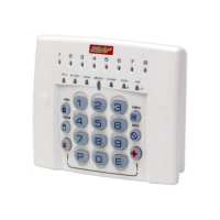
KPX keypad
Maximum 3 keypads per system.
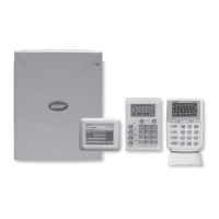
SATURN keypadNAVIGATOR keypad*
*NAVIGATOR keypad is compatible
with D8x/D16x control panels
version 7.0 or later
+12V
Red
DA
TA
White
RSSI
Blue
OV
Black
100-200
Ness Radio Interface.
#
The Weigand Interface and Ness PD
both connect to the READER
header. Weigand Interface may be
temporarily disconnected to use the
Ness PD.
Blu
Brn
Grn
Wht
Red
Blk
1
2
3
106-012 Weigand
Interface.
Provides connection
for up to 3 addressable
Weigand Readers (Ness
101-014).
See page 78.
106-017 Ness PD
Portable Download
Tool. Allows easy
on-site copying and
re-loading of D8x/
D16x programming
options without a PC.
Requires D8x/D16x
version 7.4 or later.
NESS PD
106-017
D8X / D16X
PORTABLE
DOWNLOAD
READER
#
header
READER
#
header
RECEIVER
header
The Relay Board and the Output Expander Board connect to
the Aux header on the D8x/D16x main board but you cannot
connect both at the same time. If required, the Relay Board
can be driven by outputs from the Output Expander.
0V
+12V
AUX4
AUX3
AUX2
AUX1
NO C
AUX1
NC NO C
AUX2
NC NO C
AUX3
NC NO C
AUX4
NC
106-013 Relay Board.
Provides 4 relay
outputs suitable for
switching low voltage
accessories.
Connect up to one
additional expander
OUT
12V In
12345678910111213141516
+
IN
106-011 Output Expander.
Provides 16 programmable
open collector outputs.
See page 54.
AUX header
AUX header
450-185
Serial Cable.
Used for two-way
serial comms or
direct connect to
a PC.
SERIAL
header
PC Serial
port