212
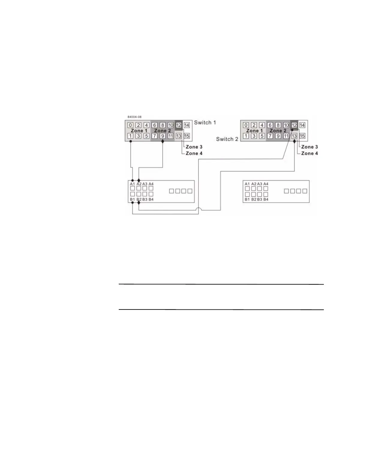
6. Connect controller port A1 of the primary storage array to an available port in
zone 1 of switch 1.
The following figure shows the connection that is described in step 6 through
step 9.
Figure 17 Primary Storage Array Connections to Fibre Channel Switches
7. Connect controller port B1 of the primary storage array to an available port in
zone 3 of switch 2.
8. Connect controller port A2 of the primary storage array to an available port in
zone 2 of switch 1. In a four-host-port system, connect controller port A4 to an
available port in zone 2 of switch 1.
9. Connect controller port B2 of the primary storage array to an available port in
zone 4 of switch 2. In a four-host-port system, connect controller port B4 to an
available port in zone 4 of switch 2.
NOTE Upon activation of the Synchronous Mirroring premium feature, controller
port A2 and controller port B2 are reserved for mirror relationship synchronization. In
a four-host-port system, controller port A4 and controller port B4 are reserved.
10. Connect controller port A1 of the secondary storage array to an available port in
zone 1 of switch 1.
The figure following step 13 shows the connection described in step 10 through
step 13.
11. Connect controller port B1 of the secondary storage array to an available port in
zone 3 of
switch 2.
12. Connect controller port A2 of the secondary storage array to an available port in
zone 2 of switch 1. In a four-host-port system, connect controller port A4 to an
available port in zone 2 of switch 1.