INSTALLATION GUIDE
6. PHYSICAL INSTALLATION OF THE APPLIANCE
6.2.1.2 View from the front
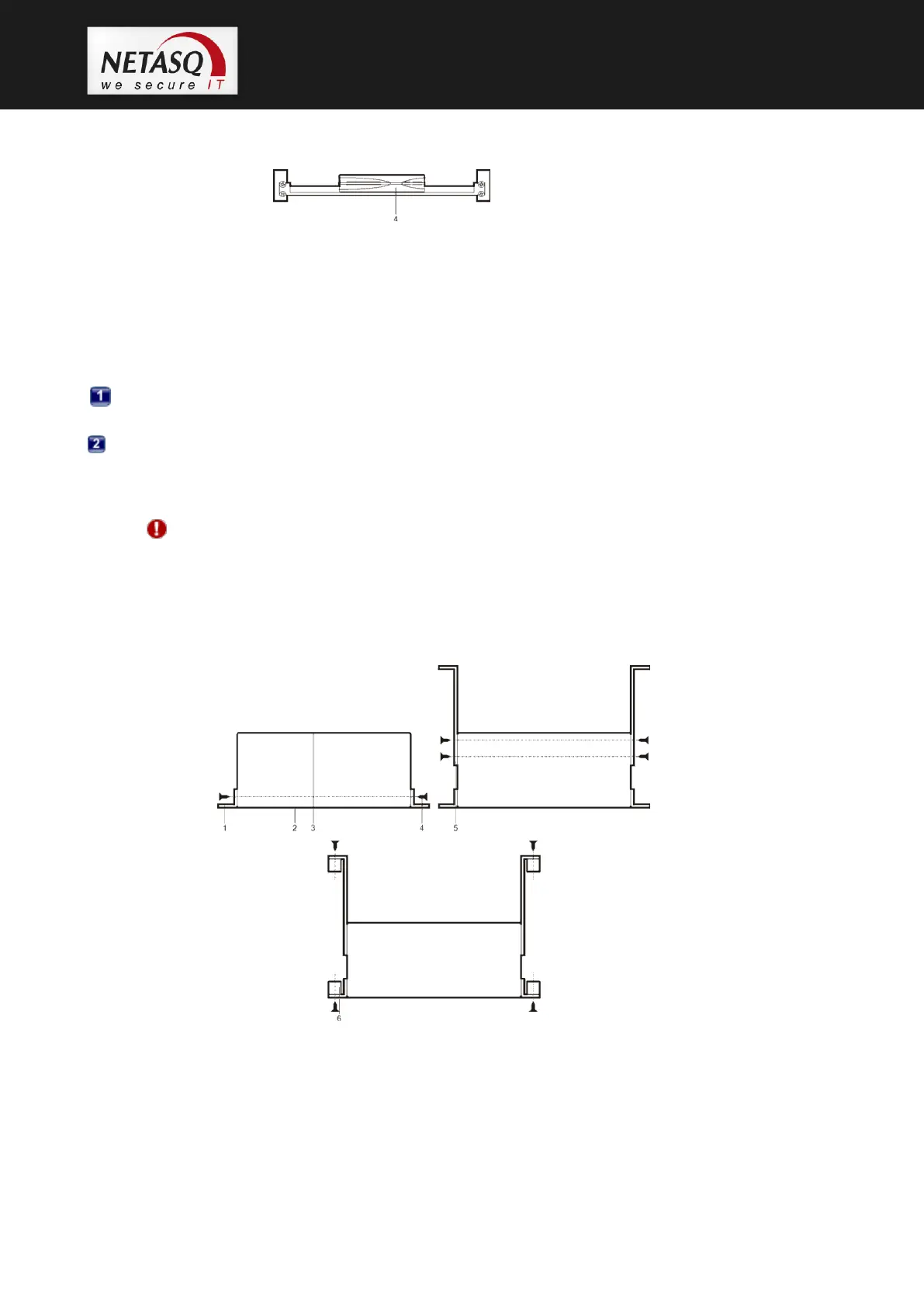
Figure 20: U30,U70: Installation in a bay - View from the front
1. Lateral bars in the bay
2. Supporting deck
3. Screws and caged nuts
4. Appliance
A system for installing the appliance in a bay can be delivered for the U30 by special order:
Installation of the deck in the bay. Screw the supporting deck to the lateral sides of the rack
using the caged nuts.
Once the deck has been installed, you will be able to place on or two products (no fastening is
needed) on the supporting deck.
WARNING
Ensure there is space of 1U above the product for proper air circulation.
6.2.2 Installing a U120, U250 or U450
Figure 21: U120, U250, U450: Installation in a bay
1. Lateral bars in the bay
2. Front panel
3. Rear panel
4. Screws and caged nuts