INSTALLATION GUIDE
6. PHYSICAL INSTALLATION OF THE APPLIANCE
U120 appliances are delivered with a set of brackets for mounting the appliance in a bay. These
brackets are not shown in the diagram above.
Installation of the firewall in the bay. Screw the lugs of the chassis to the lateral sides of
the bay.
WARNING
The metal handles on the front panel of the product should not be used for lifting it, but only
for setting it in or removing it from the bay.
6.2.3 Installing a U1100, U1500 or U6000
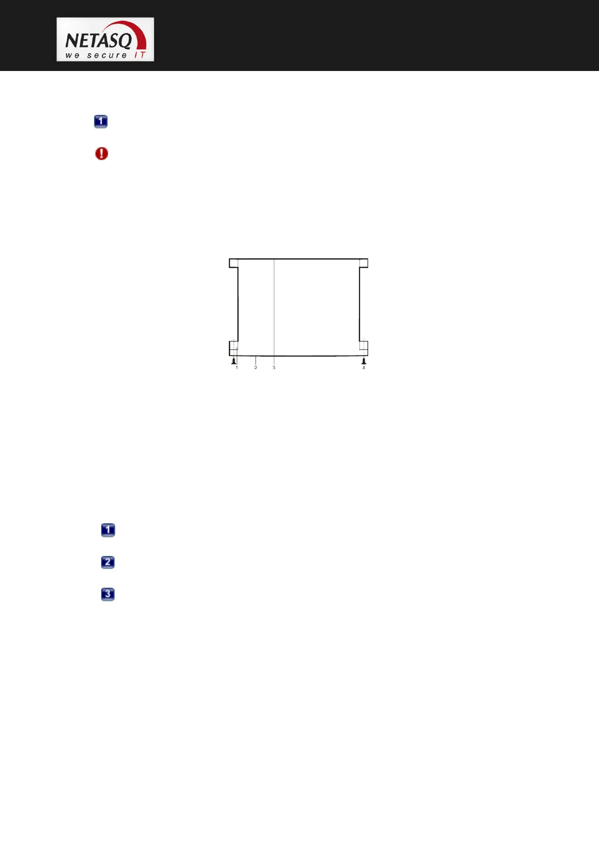
Figure 22: U1100, U1500, U6000: Installation in a bay
1. Brackets
2. Front panel
3. Rear panel
4. Screws and caged nuts
5. Supporting rail
6. Lateral bars in the bay
U1100 appliances are delivered with a system of brackets to be attached to the front panel of the
appliance and lateral supporting rails.
Setup of the supporting rails. Screw the brackets to the appliance. The lugs have to be
placed at the front panel of the product.
Setup of the supporting rails. The positioning of the supporting rails depends on the
size of the bay.
Installation of the appliance in the bay. Screw the brackets and supporting bars to the
lateral sides of the bay.
6.2.4 Preconfiguring a firewall
You can now connect to the firewall through the NETASQ configuration graphical interface,
NETASQ UNIFIED MANAGER.
After you have installed this configuration software on your client workstation, you can modify the
parameters of the network interfaces on the NETASQ firewall in order to adapt it to your IP
addresses and to select the operating mode (transparent or normal).
If you had changed the IP address of the Windows client workstation for this configuration, don’t
forget to reset it to its former configuration.