Hardware Setup
10
N150 Wireless ADSL2+ Modem Router DGN1000
Front Panel
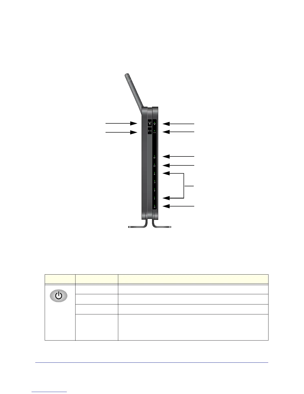
The following figure shows the status LEDs and icons on the wireless modem router front
panel. Note that the Wireless and WPS icons are buttons.
Power
LAN Ports
DSL
Internet
Wireless
WPS
Wireless On/Off button
WPS On/Off button
Figure 5. Front panel LED Icons
The tables describe the LEDs, icons, and buttons on the front panel from left to right.
Table 1. Power On/Off button
Icons LED Activity Description
Solid green. Power is supplied to the router.
Solid red POST (power-on self-test) failure or a devi
ce malfunction has occurred.
Off Power is not supplied to the router.
Restore Factory
Settings
Light blinks momentarily when the Restore Fa
ctory Settings button on the
bottom of the unit is pressed for 6 seconds. The Power LED then blinks red
three times when the Restore Factory Settings button is released and then
turns green as the gateway resets to the factory defaults.