HX4E/MX8A Series Voice Gateway User Manual
www.newrocktech.com 5
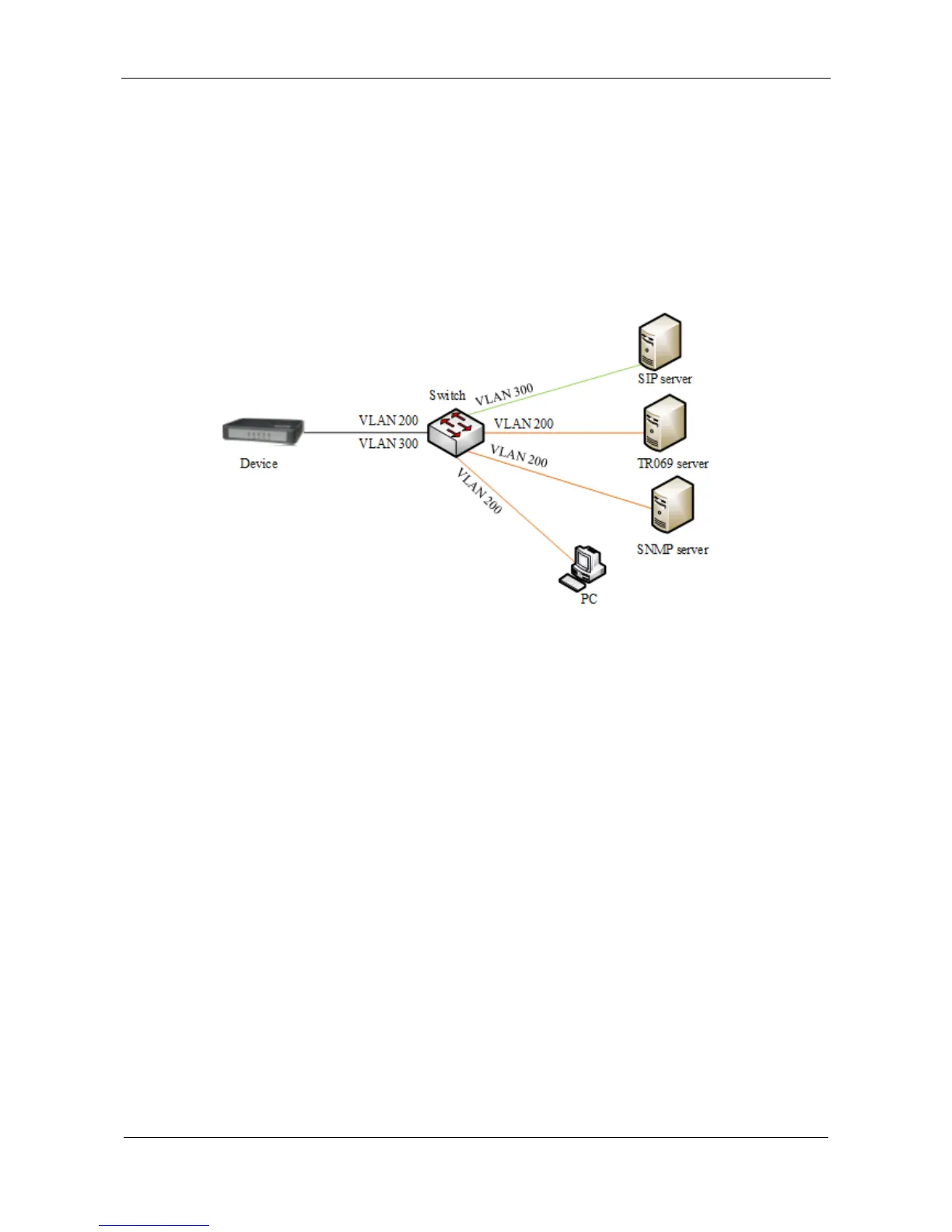
Example of Multi-service VLAN
Figure 3-68 shows the network environment. The ports for connecting the switch and HX4 are added
to VLAN 200 and VLAN 300. The port for connecting the switch and SIP server is added to VLAN
300. The ports for connecting the switch to the PC (used for managing HX4), TR069 server, and
SNMP server are added to VLAN 200.
Figure 3-68 Network environment
1. Configure multi-service VLAN on the HX4 device: the voice VLAN uses mode 1, the VLAN tag is
300, the VLAN tag of the management VLAN is 200, and the IP address is obtained from the
corresponding VLAN network using DHCP. As shown in Figure 3-69.