61
with high precision in real-time. Increases in the refractive index at the sensor surface, caused
by, for example, a binding event to the sensor, causes the LSPR absorbance peak to shift to higher
wavelengths.
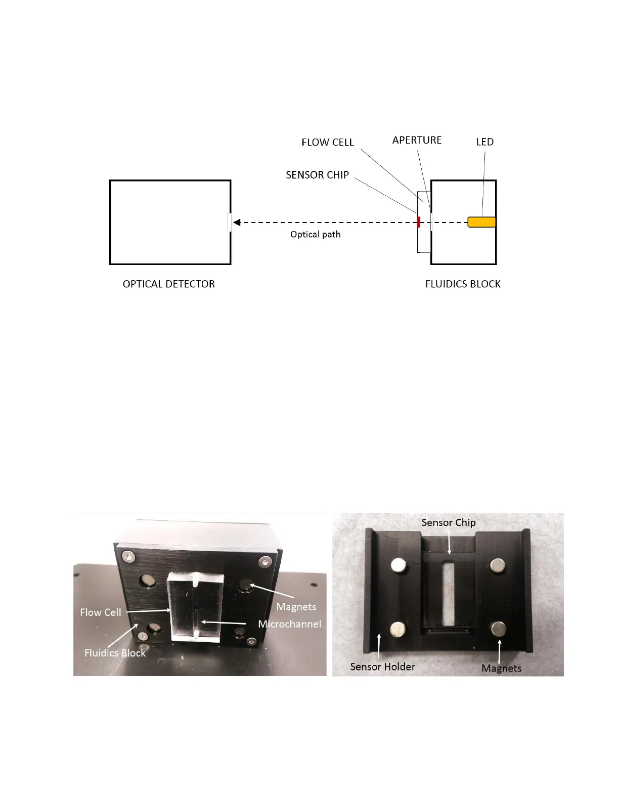
Figure 4.4 - OpenSPR™ optical system diagram (top view). Note sample holder is not shown.
The fluidic system is essential to introducing analyte to the sensor surface in a consistent and
repeatable manner. A peristaltic pump is used to continuously pump running buffer through the
Flow Cell and over the sensor surface. The fluidics between the peristaltic pump and the Flow
Cell is interfaced with the XT autosampler and is further described in the next section. The Flow
Cell is made of a polymeric material containing a microfluidic channel which seals to the surface
of the Sensor Chip using pressure [Figure 4.5 - left]. In this manner, the Sensor Chip forms one
side of the microchannel as shown in the image below [Figure 4.6]. The Flow Cell Inlet and Outlet
are connected to the rest of the fluidic system through connections in the Fludics block. The
Sensor Chip is loaded into a slot in the Sensor Holder, and magnets in the Sensor Holder and
Fludics block provide the force and alignment necessary to seal the Flow Cell to the sensor [Figure
4.5 - right].
Figure 4.5 - Fluidics Block and Flow Cell (left) and corresponding sample holder containing Sensor Chip (right).