Training Guide Course No. 196514
Level 2 Maintenance, X-1000 Series Dispensing Systems 4-100 P/N 196515 (Revision A)
Is mechanical
correction required as
a result of the above
inspections?
Resolve and go to Facility
Power and Air Supply
Verification
Go to Facility Power and
Air Supply Verification
• Look for loose sensor mounting hardware.
• Look for damaged electrical cables.
• Look for disconnected or poorly secured electrical cables.
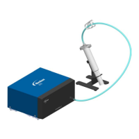
• Look for disconnected or poorly secured Fiber-optic Cables
to the Sensor Amplifier.
• Look for nicked, cut, or pinched Fiber-optic cables.
Perform the following inspections:
Yes No
Is mechanical
correction required as
a result of the above
inspections?
Is mechanical
correction required as
a result of the above
inspections?
Resolve and go to Facility
Power and Air Supply
Verification
Go to Facility Power and
Air Supply Verification
• Look for loose sensor mounting hardware.
• Look for damaged electrical cables.
• Look for disconnected or poorly secured electrical cables.
• Look for disconnected or poorly secured Fiber-optic Cables
to the Sensor Amplifier.
• Look for nicked, cut, or pinched Fiber-optic cables.
Perform the following inspections:
Yes No
Diagram Sheet 4-8-1
Board Sensor Fault Isolation Procedure – Mechanical Verification

 Loading...


