System Setup
3-2
Part 1602221-01
E 2012 Nordson Corporation
Controller Rail Mounting (contd)
4. Install the rail bracket over the operator platform railing (6), tighten the
screws (3) against the rail, then tighten the jam nuts (4) up against the
rail bracket to prevent the screws from loosening.
5. Install the parts tray (11) in the front two holes on top of the controller
using two of the M5 screws (2) in the controller top, and one #10 dished
lock washer (9) included in the kit.
6. Use the bus-bar grounding kit to connect the controller ground stud to
the booth base, as described in the grounding kit instructions.
System Connections
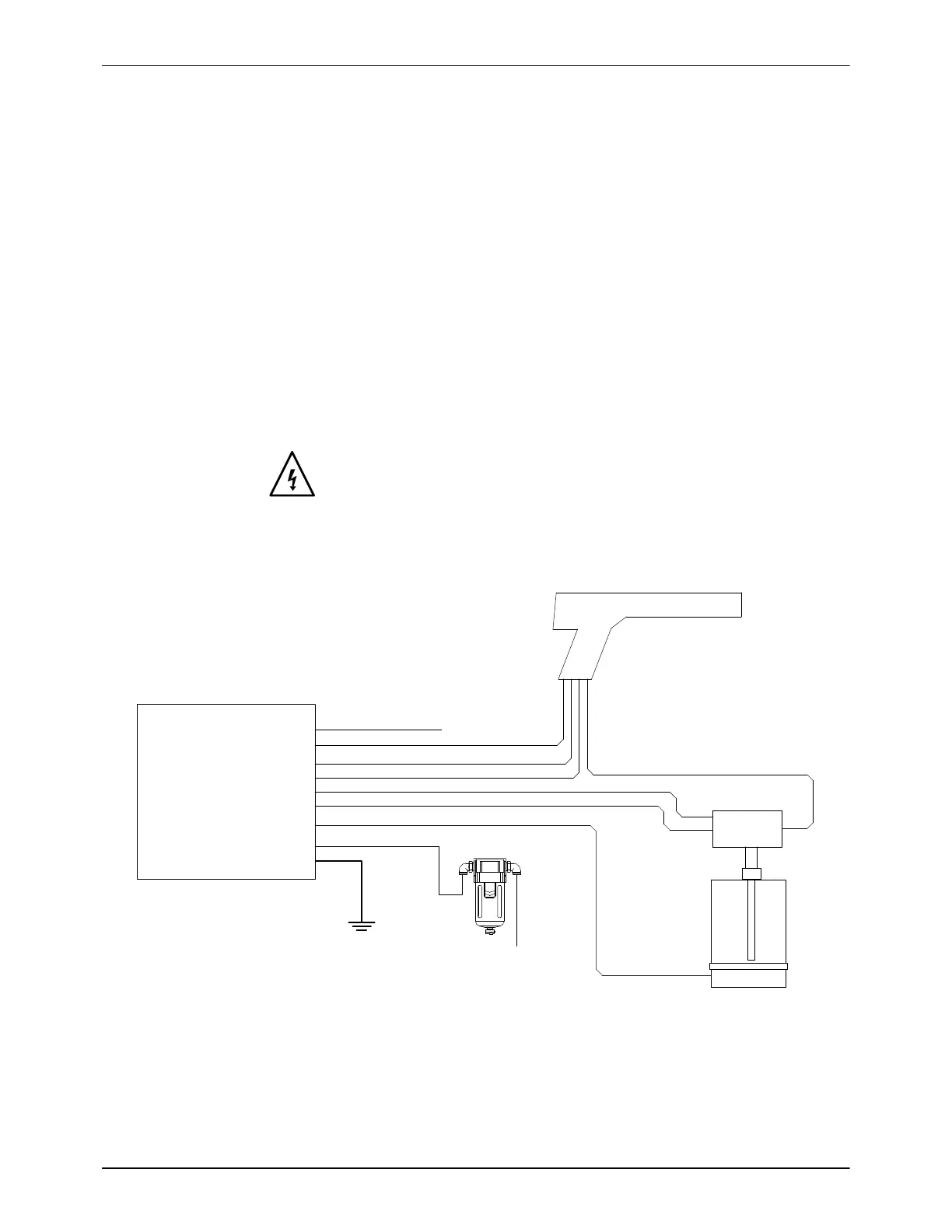
System Diagram
WARNING: This diagram does not show all system grounds. All conductive
equipment in the spray area must be connected to a true earth ground.
NOTE: The filter and mounting bracket are shipped in a kit for mounting at
the customer’s plant.
AC Power Cord
Gun cable
6mm black
4mm clear
8mm blue
8mm black
6mm blue
Spray Gun
Powder hose
Pickup Tube
Pump
Input Air
10mm
Filter
Encore LT
Controller
Ground
Feed
Hopper
10mm
Electrode Air Wash
Purge Air
Atomizing Air
Flow Air
Fluidizing Air
Figure 3-2 Powder System Block Diagram