System Setup
3-7
Part 1602221-01
E 2012 Nordson Corporation
Power Supply
The spray gun controller is rated for 100−240 Vac at 50/60 Hz, single phase.
To provide power to the controller, wire the controller power cord to an
electrical panel or to a customer-supplied three-prong plug. Regardless of
the installation, power should be provided through an external disconnect
switch with lockout capability.
Wire Color Function
Blue N (neutral)
Brown L (hot)
Green/Yellow GND (ground)
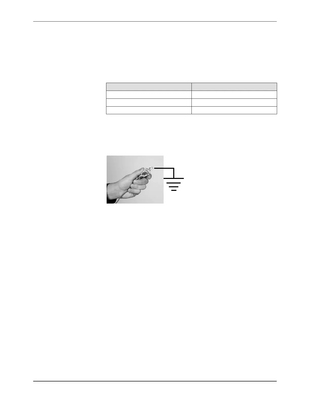
System Ground
See Figure 3-7. Connect the ground cable attached to the controller ground
stud to a true earth ground.
Figure 3-7 System Ground Connection
Rail Mount Systems: Locate the ESD grounding block kit. Follow the kit
instructions to install the grounding block to the grounded spray booth base.
Connect the flat braided ground cable from the controller ground stud to the
grounding block.
Controller Configuration
Power Up Sequence
When power is applied to the system, the controller goes through the
following sequence:
1. All displays and LEDs light for 3 seconds.
2. The main control board configuration is displayed on the KV/μA panel:
A: Auto (refer to troubleshooting to change the jumper if A is displayed)
H: Manual
3. The controller software and hardware version are displayed on the
KV/μA panel in the form N.NN for 1 second.
NOTE: If the spray gun is triggered on during power-up or wake up from
disable, the trigger LED blinks at a fast rate. Release the trigger and repeat
the sleep/wake up cycle.