Repair
6-9
Part 1602221-01
E 2012 Nordson Corporation
6. To remove the switch, cut the ribbon cable, or feed the bottom of the
switch through the slot in the trigger recess and remove it from the
handle.
Switch Installation
NOTE: A new axle (43A) is included with a replacement trigger switch.
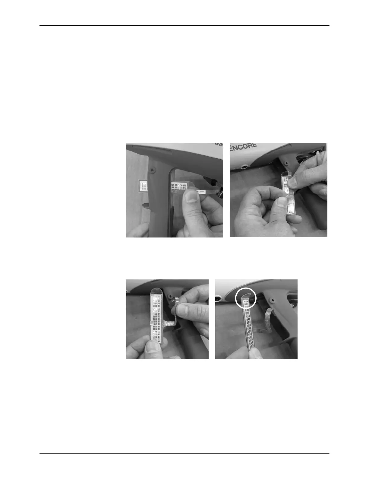
1. See Figure 6-9. Orient the new switch with the grid facing away from the
inlet tube, then carefully feed the square bottom end of the switch
around the left side of the inlet tube and through the slot in the trigger
recess.
2. Peel off the small piece of tape holding the ribbon cable against switch.
Figure 6-9 Installing the Trigger Switch − Steps 1 and 2
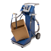
3. See Figure 6-10. Straighten the ribbon cable, then bend the pull tab at
the top of the switch so that it is perpendicular to the switch.
Figure 6-10 Installing the Trigger Switch − Step 3
4. See Figure 6-11. Peel the adhesive release liner from the switch.
5. Carefully install the switch, pull tab up, against the bottom and right
edges of the trigger recess.
6. Make sure the ribbon cable is not trapped or pinched, then press the
switch against the back of the recess. Run your finger up and down on
the switch to ensure it is securely adhered to the handle.